


I3C and I2C are both two-wire communication protocols that help exchange data between multiple devices. While I3C preserves the simplicity of I2C, it introduces new features suited for today’s sensor-rich devices.
Inside every electronic system, from smartphones and laptops to massive data centre servers, there are many small components or peripherals that must communicate with a central controller. These include sensors that monitor temperature and voltage, EEPROMS that store configuration data, and power management ICs.
All these peripherals work together to keep the system running smoothly. However, connecting each component with its own set of wires would make the board complex, messy and costly. To overcome this, engineers use shared communication buses, where devices use the same wires and take turns to communicate.
One of the simplest and most used protocols for this purpose is I2C (inter-integrated circuit) — a two-wire communication protocol to exchange data between multiple devices.
In server environments, I2C plays an essential role inside the baseboard management controller (BMC), which is a dedicated chip responsible for monitoring the system health, reading sensors, managing power rails, and more. I2C acts as the communication path behind the BMCs to monitor and control different parts of a running server.
How I2C works
I2C is a bus interface connection protocol incorporated into devices for serial communication. It uses only two bi-directional open-drain lines (as shown in Figure1):
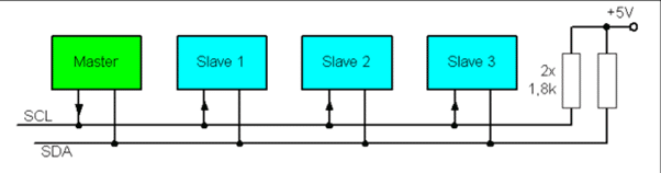
- SDA (serial data line), which carries the actual data bits
- SCL (serial clock line), which carries the clock signal
Each device connected to these lines acts as either a master (which initiates communication) or a slave/target (which responds).
A device can only pull the bus line to LOW (0), and it never drives the line HIGH (1). When the device releases the line, an external pull-up resistor pulls the line up to HIGH (as shown in Figure 2).
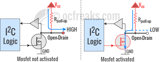
So, each device has two states for the bus pin:
- Drive LOW: Turn ON the transistor → line connects to GND → 0
- Release: Turn OFF the transistor → line floats → pull-up resistor makes it 1
Open-Drain
This open-drain signalling ensures safe, collision-free communication:
- Any device can pull the line LOW.
- No device ever forces it HIGH.
- If two devices send data at once, the LOW signal always dominates, preventing conflict.
This design enables two powerful features:
Arbitration: Multiple masters can attempt communication without corrupting data.
Clock stretching: Slower devices can hold the clock LOW to pause communication until they’re ready.
This is critical in a server motherboard, where various controllers (such as the CPU’s power controller and BMC) may share the same I2C bus. Without open-drain logic, they could interfere with each other and destabilise system monitoring.
SCL line
This is how the SCL line works in I2C communication:
Master pulls SCL LOW: The master actively pulls the SCL line LOW to begin a clock cycle.
While SCL is LOW, the transmitter sets the data (SDA): The device transmitting the data (master or slave) drives the SDA line to either logic 0 or logic 1.
Data is allowed to change only when the SCL line is LOW.
Master releases SCL (floating state): The master stops pulling SCL LOW and releases the line.
Pull-up resistor pulls SCL HIGH: Since no device is pulling the line LOW, the pull-up resistor drives SCL HIGH.
When SCL is HIGH, the receiver samples SDA: The receiving device reads the SDA line while SCL is HIGH. The data must remain stable during this period.
Steps of I2C data transmission
The I2C follows the steps given below to transmit data (as shown in Figure 3):
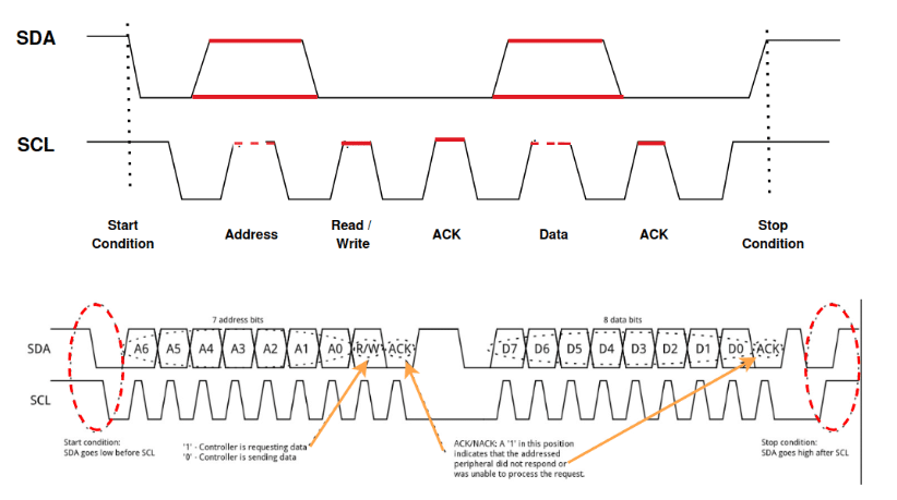
Start condition: The master device sends a start condition by pulling the SDA line low while the SCL line is high. This signals that a transmission is about to begin.
Addressing the slave: The master sends the 7-bit address of the slave device it wants to communicate with, followed by a read/write bit. The read/write bit indicates whether it wants to read from or write to the slave.
Acknowledge bit (ACK): The addressed slave device responds by pulling the SDA line low during the next clock pulse (SCL). This confirms that the slave is ready to communicate.
Data transmission: The master or slave (depending on the read/write operation) sends data in 8-bit chunks. After each byte, an ACK is sent to confirm that the data has been received successfully.
Stop condition: When the transmission is complete, the master sends a stop condition by releasing the SDA line to HIGH while the SCL line is HIGH. This signals that the communication session has ended.
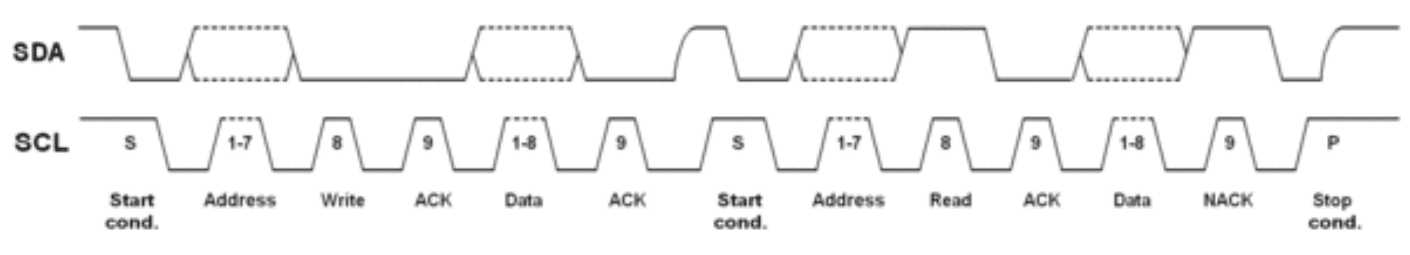
Repeated Start
Sometimes the master needs to first write something to a device (like a register address), and then immediately read data back from the same device.
If the master sends a STOP and then a new START, another master could take control of the bus in between. That would break the transaction. Instead, the master uses ‘Repeated Start’. This is another START condition without sending STOP first. So the bus is not released.
This means that no other master can interrupt and the same device continues the conversation.
Clock stretching: When the slave needs more time
The master controls the clock (SCL) but some devices are slow. Examples are:
- EEPROM writing to flash
- Sensor doing internal conversion
- PMIC updating measurements
If the master keeps sending clocks, the slow device may not be ready.
As discussed earlier, I2C uses open-drain signals so anyone can pull the line LOW and nobody forces it HIGH.
During communication the master releases SCL (tries to make it HIGH). If slave is not ready, it pulls SCL LOW. The clock stays LOW and there is a pause in the communication. When slave is ready, it releases SCL. The pull-up resistor makes SCL HIGH, and the clock continues.
So the slave controls time, not the master.
Arbitration: When two masters talk at the same time
I2C supports multi-master systems. This means both the CPU controller and the BMC can be masters. Both are connected to the same bus.
When both devices start at the same time without arbitration, signals collide, data becomes garbage, and the bus crashes. So, I2C uses bit-level arbitration.
A key rule is that LOW always wins.
Because of open-drain:
- Sending ‘1’ → device releases line (goes HIGH by pull-up)
- Sending ‘0’ → device pulls line LOW
If one device sends ‘1’ and another sends ‘0’, the actual bus level equals LOW.
Here’s an example of arbitration.
Two masters start at the same time: Master A and Master B both send START (as shown in Figure 5).
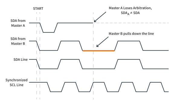
Step 1: Both send address bits:
Master A sends bit = 1 (releases SDA)
Master B sends bit = 0 (pulls SDA LOW)
Step 2: Bus becomes LOW. Both read the bus:
Master B: I sent 0 and I see 0 → OK
Master A: I sent 1 but I see 0 → I lost!
Step 3: Master A stops transmitting. It switches to listening mode.
Step 4: Master B continues alone. No data corruption, no reset and no crash.
This happens bit by bit, not byte by byte. So arbitration is fast and safe.
Limitations of I2C
While I2C is simple, modern systems like smartphones and servers are more demanding. Some of its limitations include:
Limited speed: Even Fast-mode Plus (1MHz) isn’t enough for high-throughput sensors or large server systems that need real-time readings.
No in-band interrupts: Devices can’t signal the master about urgent events without a separate GPIO interrupt pin.
Fixed addresses: Static addressing can cause conflicts when multiple identical sensors are used — common in large boards like server motherboards.
Higher power use: Pull-up resistors constantly draw current when lines are low, which can add up in energy-sensitive systems.
As embedded system complexity grew, particularly in modern servers with hundreds of sensors and monitoring ICs, these weaknesses drove the development of a more advanced replacement: I3C.
Introducing I3C: Smarter, faster, and more efficient
I3C stands for improved inter-integrated circuit. It keeps the same two-wire design but upgrades it for today’s needs. It’s backward compatible with I2C, which means older devices can still connect, but it offers major enhancements like faster communication speeds, Dynamic (runtime) Address Assignment, In-Band Interrupts, and lower power operation.
For server platforms, this means better performance for the BMC and faster sensor polling — all with fewer wires and less power draw. I3C is becoming an integral part of next-generation server management and data centre monitoring infrastructures.
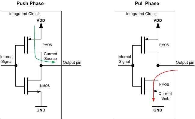
I3C bus uses both open-drain and push-pull. Open-drain is used for initialisation and arbitration, while data transfer is used for push-pull.
In push-pull a device can actively drive the line both LOW and HIGH. It connects the line to the ground to send a logic 0 and connects it to the supply voltage to send a logic 1.
Push-pull outputs do not require pull-up resistors and are typically used in point-to-point or single-driver communication interfaces.
Open-drain to push-pull switching in I3C is as follows:
- The I3C bus always starts in open-drain mode to maintain backward compatibility with legacy I2C devices and to support arbitration during bus initialisation.
- Once dynamic addresses are assigned and only one target is selected for a private transfer, arbitration is no longer required.
- In this phase, the master and the selected I3C target may use push-pull signalling on the SDA line to achieve higher data rates and faster signal transitions.
- If legacy I2C devices are present on the bus, they do not respond to CCC (common command codes) such as ENTDAA. The master must continue to use open-drain signalling for bus management and any I2C-compatible transactions.
- However, push-pull signalling can still be used for private I3C transfers to I3C targets, while ensuring that electrical compatibility with I2C devices is maintained.
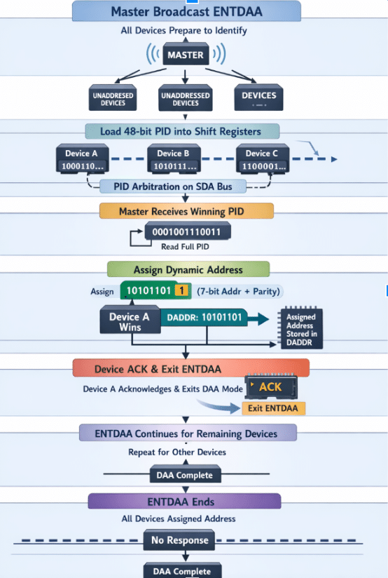
During ENTDAA (Enter Dynamic Address Assignment), devices do not yet have addresses. So for identifying the devices, they use PID (48 bits). PID contains:
- Vendor ID (who made the chip)
- Part ID (model of the chip)
- Instance ID (which copy of the chip it is)
All chips have a globally unique identity. This is how arbitration works safely.
Dynamic Address Assignment flow
- Master broadcasts ENTDAA: All devices without a dynamic address prepare to identify themselves.
- All unaddressed targets prepare to respond: Each target loads its 48-bit PID into shift registers. The device copies its internal 48-bit ID into hardware that can send one bit per clock on the SDA line and monitor the bus for arbitration, which is required for DAA in I3C.
- PID arbitration: The device with the lowest PID value wins. The master receives the full PID of the winning device.
- Master assigns dynamic address: 7-bit address + parity bit (to detect errors; parity = 1 if the number of 1’s is even, and parity = 0 if the number of 1’s is odd). The device accepts the address and stores it in the hardware register inside it (DADDR).
- Device ACKs and exits ENTDAA: The device does not participate again in DAA and uses the dynamic address from now on.
- ENTDAA continues for remaining devices: The same process continues until no devices respond anymore.
- ENTDAA ends: When the master sees no response during the ENTDAA phase, it knows that all devices have been assigned addresses.
In-Band Interrupts — Devices can call for help
In I2C, if a sensor has a problem, it cannot easily alert the master. It needs extra wires. In I3C, devices can send alerts directly on the same bus using In-Band Interrupts (IBI).
For example, if temperature suddenly rises in a server, the sensor sends IBI to BMC, which reacts immediately (increase fan, shutdown, alert admin). This is done without using extra wires, which is very useful in dense server boards.
Where I2C and I3C are being used today
| Bus type | Common applications |
| I2C | EEPROM storage, temperature sensors, RTCs, fan controllers, basic power monitors, legacy server BMC communication |
| I3C | Sensor hubs in mobile devices, camera modules, SoC integration, server BMC-sensor communication (next-gen IPMI replacements), high-speed telemetry systems |
I2C became widely adopted because of its simplicity, low hardware cost, and reliability. It remains suitable for low-speed and low-complexity peripherals. However, modern embedded systems demand faster communication, lower power consumption, and better scalability.
I3C preserves the simplicity of two-wire communication while introducing features such as dynamic address assignment, in-band interrupts, and push-pull signalling, making it suitable for today’s high-performance sensor-rich systems.
Seen together, I2C and I3C show how good standards grow over time. We don’t throw away what already works; we build on it and extend it so it can handle the demands of newer, more advanced hardware.


