


Autonomous cars are the future. A lot of work goes into designing them to minimise the risk of machine failure and accidents. This article outlines how Node-RED can be used to create flows for developing animations of car movements.
Autonomous cars are set to revolutionise the travel experience for all of us. As per a Gartner report, there were 508,622 autonomous cars on the road in 2021. This figure is expected to go up to 745,705 in 2023. Autonomous cars reduce the possibility of accidents caused by driver distraction, reduce traffic congestion, and optimise the use of fuel. Cameras, radars, and ultrasonic and touch sensors used in these cars replace human decision-making. This article outlines how to enhance the capability of these cars by creating Node-RED flows that develop animations for car movements. The flows are implemented and the movements are observed with various input and output sequences, using the animations developed.
Node-RED
Node-RED is open source software used for the Internet of Things (IoT) and for making Web applications. Unlike normal software that use complex programs and structures, Node-RED uses GUI operations to create ‘flows’ that are easy to understand. This is done by integrating various ‘nodes’ without using any complex code. Similar to the successful serverless architecture, the zero coding techniques of Node-RED are gaining popularity for IoT operations. Node-RED allows us to develop real-time applications in IoT, online services and projects with minimal effort. This article will help you create a pleasant graphical representation of blocks named ‘nodes’ in Node-RED, which provide programmers a fantastic way to develop applications. It can also function as a wiring tool that can connect a large number of both hardware and software devices.
Node-RED development environments can also connect hardware devices to Web services. Users can share their flows with each other, making group based activities convenient. Node-RED can be used both for simulation and real-time applications. In this article, the simulation mode is explored for the animation of autonomous cars.
Installation of Node-RED and associated components
The latest version of Node.js can be installed from the URL https://nodejs.org/en/download/. The checkup wizard for the same can be completed with full administration permissions sanctioned.
To check if Node.js has been installed successfully, without any issues, the following command is used. This also checks the version installed.
node-v
After its setup, the node package manager (NPM) is installed by typing the command given below:
npm install –g node-red
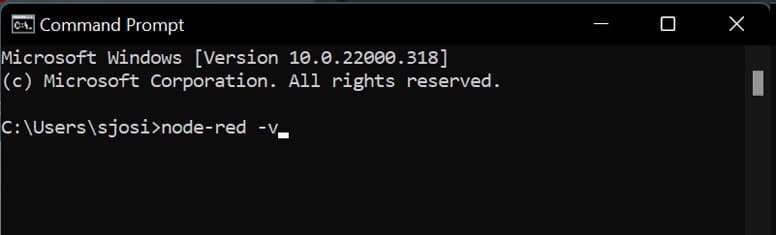
To check the installation status or version of Node-RED, give the following command. This command shows the verbose output while the server is being started, as shown in Figure 1.
node-red –v
After the installation, to view the default Node-RED screen, the website must be opened with the URL http://127.0.0.1:1880 using the browser. This URL address notifies that we have the Node-RED server running on the local machine on port 1880.
To install the SVG graphics node, the following command is to be given:
npm install node-red-contrib-ui-svg
Architecture for animation in autonomous cars
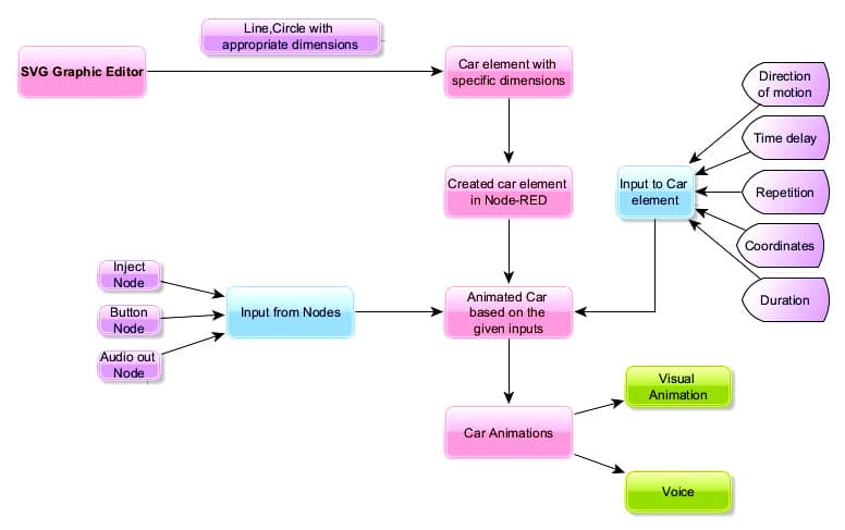
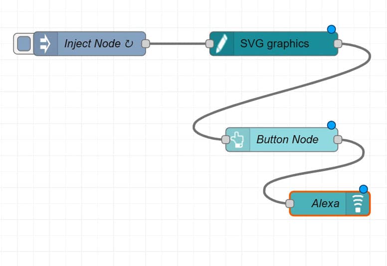
A new flow is created first, and an SVG graphics node is added. Later, a car is drawn in the SVG editor using elements like lines and circles. Next, to add animation, there should be specific parameters like direction of motion, time delay between movements, number of times the movement has to be repeated, coordinates of movement and the duration of movement. After creating the animated car, configure the ‘button’, ‘audio out’ and the ‘inject’ nodes. A connection is made between the SVG graphics, inject button and audio out nodes in the Node-RED flow. A stationary car will be visible in the Node-RED dashboard (output window) and animation is triggered once the button is pressed. The entire workflow is depicted in Figure 2.
Design for autonomous car animation
The steps for installing and opening the Node-RED interface are explained below.
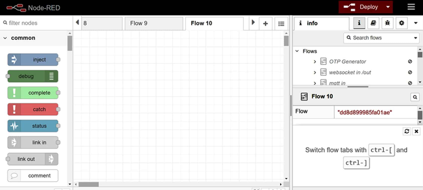
Open a new flow by clicking the ‘+’ symbol on the top right of the interface. This interface generally consists of three columns, as shown in Figure 4. In the first column, all the nodes in the node palette are visible. The second column shows the flows under operation, and the third column consists of tabs for information, debug messages, help and node configuration. The flows, sub-flows and global configuration nodes are visible under the ‘information’ tab, and the ‘help’ tab is useful for all the Node-RED libraries. The messages that are given to produce a text output are visible under the ‘debug messages’ tab. All the uses of nodes are visible under the ‘node configuration’ tab.
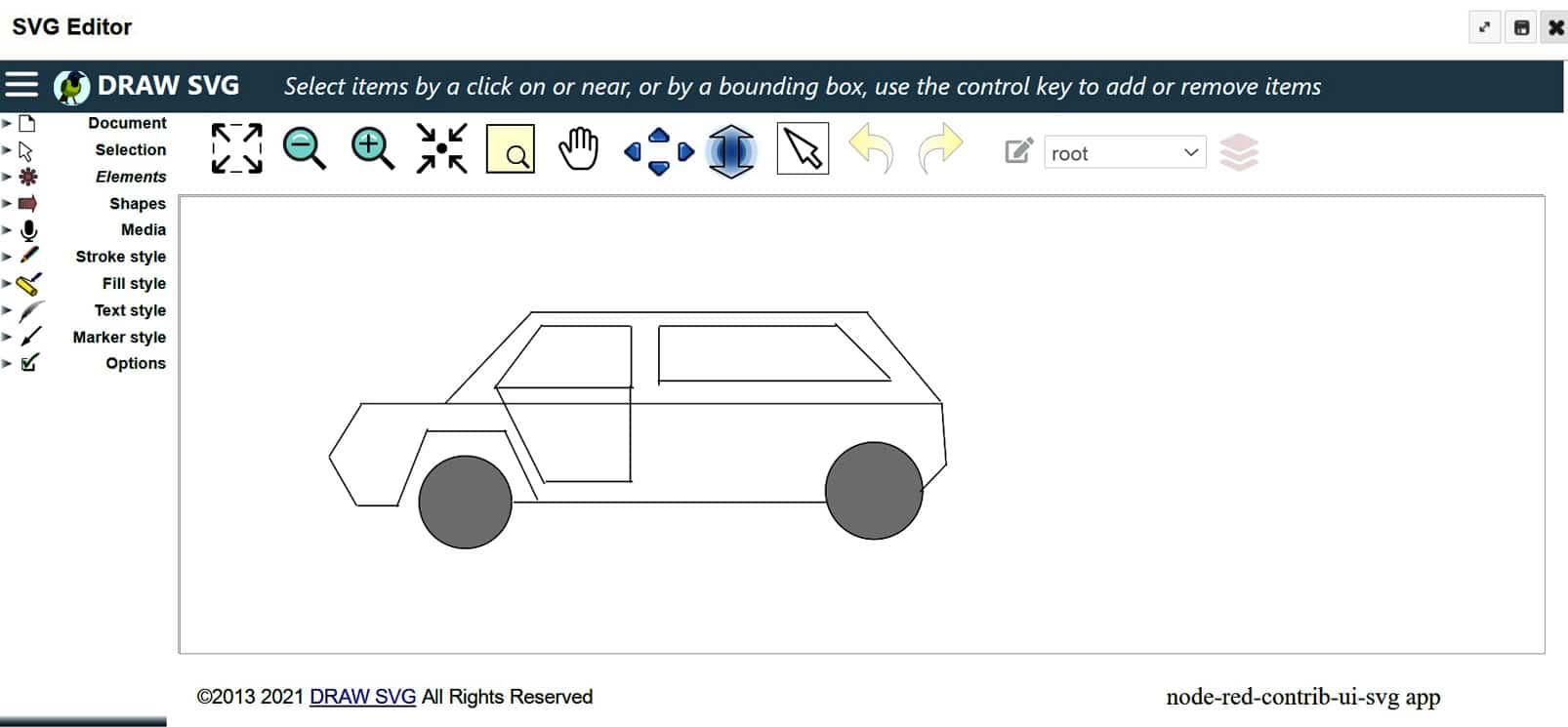
Look for the SVG graphics node in the node palette and insert it into the created flow. When it is opened, the SVG editor appears. The various options required for a drawing, like document, selection, elements, shapes, media, stroke style, fill style, text style, marker style, etc, are visible on the left side of this editor’s window.
Select the Elements option in the editor window. Shapes, lines, images and other options are visible here. After selecting the line, shape or element to be used, drag it from the Elements option on the left side. If you wish to add colours to your drawing, then double click the specific element and go to Properties. It will have a fill style option. In the ‘fill colour’ tab, we can change the colours used for filling the closed figure elements. In the ‘stroke style’ tab, the colour, width and other properties of the drawing pencil can be modified. The ‘elements’ tab takes care of properties like ID, default style, tag and path. Any shape can be created easily using the SVG editor. Any number of shapes and lines (all sizes) can be used to create the drawing we require. In this case, a car is created with 24 lines and 2 circles, with colours filled in the wheels, as shown in Figure 5.
After drawing the car, save and close the editor. Then select the ‘events’ tab in the SVG graphics node, and add a new element. The selector is given a name (car) and ‘click’ is the action for stimulation. The messages ‘car has started’ and ‘#car’ are given in the msg.payload and msg.topic options, respectively.
Once the event tab of the SVG graphics node is configured, select the JS tab. The selector ID is given as ‘car’ and ‘click’ is given as the action for stimulation.
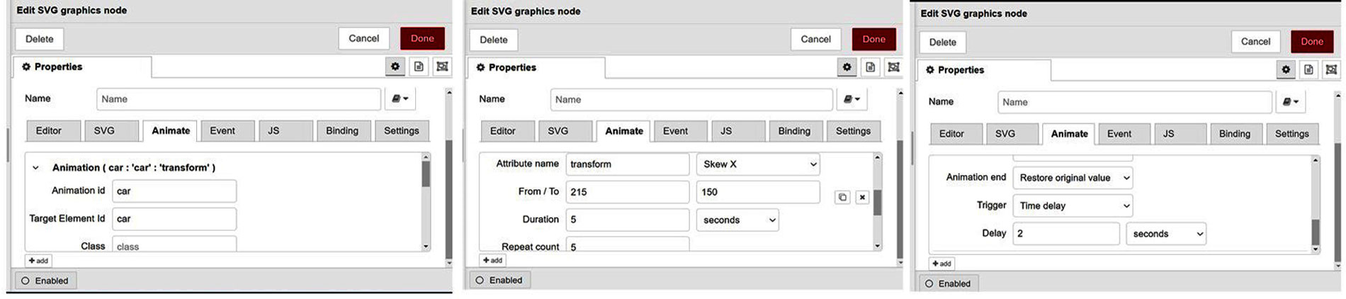
After configuring the event and JS tabs in the SVG editor, select the ‘animate’ tab and add a new element. Both the animation and target element IDs are specified as ‘car’, as shown in Figure 6. Change the attribute to ‘transform’ and the property to ‘Skew X’. Give the coordinates as 215 and 175, with a duration of 5 minutes. Set the repeat count at 5, as shown in Figure 6. Select the option to restore the original value, so that at the end of the animation the car comes to its original position. A time delay can be created in between the movements of the car. The operation in the SVG graphics node is now complete.
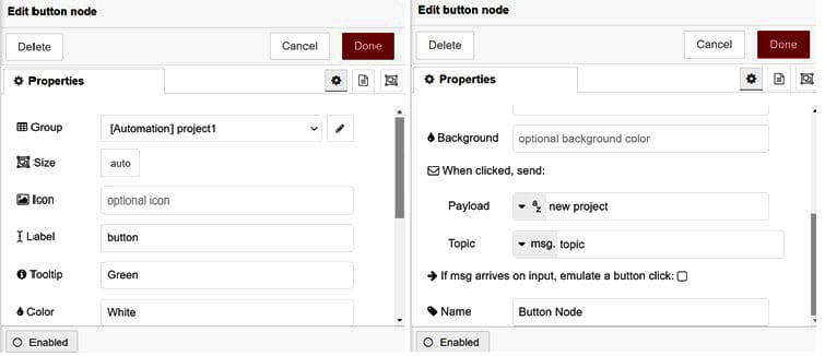
Connect the button node from the exit side of the SVG graphics node. On double-clicking, the Properties dialog box will appear. Set the group as ‘project1’ and tab as ‘automation’, as shown in Figure 7. The colour of the button can be modified. Any message can be given to the msg.payload option, as shown in Figure 7.
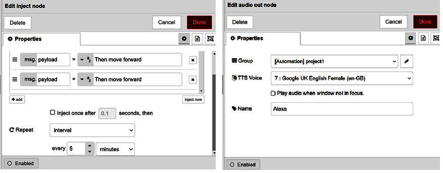
After setting up the button node, connect the inject node to the SVG graphics node. The desired input for the movement of the car can be given, so that the car moves according to the given instructions. Double-click the inject node to change its properties. The payload messages that can be given are ‘start the car’, ‘move backward’ and ‘move forward’. The animation can be made to repeat after a certain interval (5 minutes, as shown in Figure 8). Another choice is to trigger the start of the flow at a certain time every day. The audio out node is added to the flow and is wired to the button node. The group and tab are automatically set because of the connection we made between the nodes. An option is provided to choose the desired language and gender of the voice for the output, as shown in Figure 8.
After finishing the connections depicted in Figure 2, the Node-RED dashboard (output window) can be viewed by opening the URL http://127.0.0.1:1880/ui in a browser.
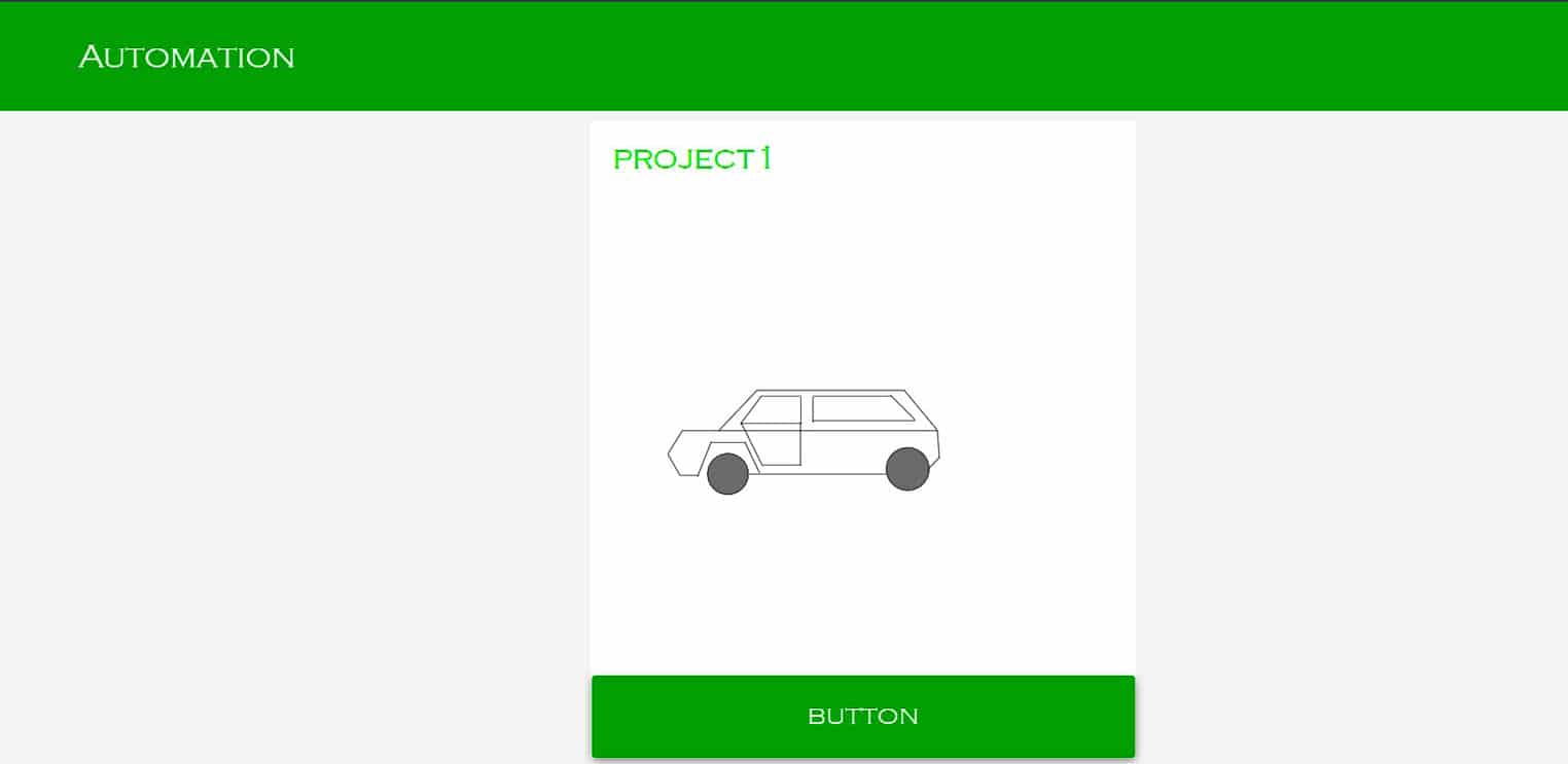
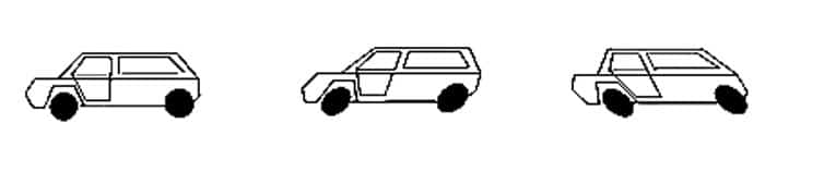
In the output window, the car is initially in a stationary position, as shown in Figure 9. Once the button is pressed, the car will move back and forth according to the values specified. This can be seen in Figure 10.
Autonomous cars can be of great help in critical locations like nuclear power plants, atomic centres, huge data centres, industrial applications with extremely high or low temperatures, and space centres. They are a great boon for the elderly and visually impaired. But they need to be designed with the utmost care to ensure there are no accidents.


