

This multi-part series of articles will take you through the various components of DevOps. It will introduce you to network function virtualization and its integration with the DevOps pipeline. This first article in the series focuses on distributed systems.
Service providers around the globe are looking for concrete solutions to provide the latest telecom applications and comply with the demands of their users. Proprietary networking devices are used to deploy these applications. While this solution fulfils customer requirements, it is not scalable and demands hefty financial investment because such hardware can easily get outdated with new technologies emerging in the market.
Network function virtualization (NFV) is seen as something that brings service providers out of this bottleneck. It is seen as a cost-effective implementation of telecommunications infrastructure. This series of articles will deal with the integration of NFV modules in a DevOps pipeline, while showcasing how various DevOps tools are interconnected to produce an environment capable of handling and deploying an NFV based infrastructure on an open source cloud.
With the advent of DevOps tools and methodologies, we now have a system for NFV applications that can be deployed and delivered in a jiffy. The various methodologies of DevOps fulfil the requirement of fast-paced delivery with easy-to-configure servers and no downtime of the application. NFV application, when orchestrated by the Kubernetes cluster, enables independent and dynamic scaling. NFV system enablement reduces the CAPEX and OPEX too. This series of articles provides step-by-step guidance on how to integrate NFV with the DevOps process.
Since the experimental work involves many technologies, we plan to publish our work in eight parts that focus on distributed systems, containerization, Kubernetes, open source cloud computing, software-defined networking, NFV, DevOps methodologies, and NFV integration with DevOps.
The need today is for fast and powerful machines that can host our applications or store important documents, which should be available around the globe. This cannot be achieved via a monolithic system design. We need something that is robust and reliable, and available from our laptops, workstations, and mobile devices. This has led to a ‘distributed system’, first coined by Paul Baran, where the idea is to create a distributed communication network in which messages are sent through a network of switching nodes until they reach the desired destination.
The distributed system we see today is different from what was envisioned back then, but the basic concept remains the same. Such a system is basically a coalition of multiple machines that are viewed as one and come together to achieve a task.
Maarten van Steen and Andrew S. Tanenbaum in their book ‘Distributed Systems’, state: “A distributed system is a collection of autonomous computing elements that appears to its users as a single coherent system.”
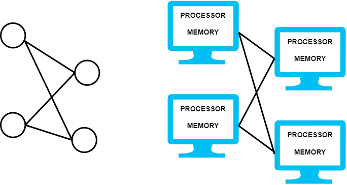
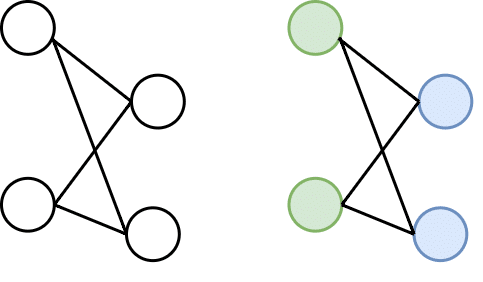
This defines two important characteristics of such systems. The first is that these are collections of multiple computing elements, which can behave and work independently but are brought together. And the second is that they are viewed by users as a single unit, so the person using such a system does not differentiate between a single unit or multiple units. We can envision these systems as a graph (Figure 1) — each computing unit is a node in that graph and each node is connected to another node via some network.
Architecture
By now we may look at distributed systems as a bunch of loosely interconnected processing devices working together over an underlying network, but there is more to this. The architectural styles define how these processing units are connected, and there are several styles:
- Layered architectures
- Object-based architectures
- Resource-centered architectures
- Event-based architectures
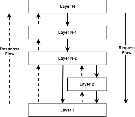
Layered architectures: The idea behind layered architectures is to organise components of distributed systems in a layered manner. Here layer Lj makes requests to Li where (i<j), and expects a response in return (as shown in Figure 2).
Object-based architectures: Here we envisage each component in distributed systems as an object. In object-based architecture (Figure 3), we see one object calling another object via a procedure-calling mechanism. This can also happen over a network via a remote procedure call (RPC). We can separate services so they can operate independently, which is today known as service-oriented architecture (SOA).
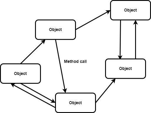
communicating with one another
Resource-centered architectures: With the growing service composition to facilitate distributed systems, there was a need to rethink the aspect of web-based distributed systems; new architecture had to be defined to optimise the usage of distributed resources. Resource-centered architectures are robust mechanisms where we can add or remove the resources to be used by applications, based on their usage. Similar resources can be retrieved or modified. These characteristics of resource-centered architectures helped representational state transfer (REST) in web-centric applications gain wide acceptance. Various RESTful operations are showcased in Figure 4.

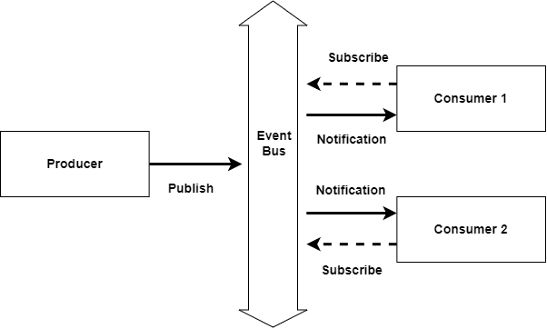
Event-based architectures: In a large set of distributed systems, we try to decouple the dependencies between the processes. The idea behind this is to view processes running autonomously, and then there is the coordination between these processes which allows communication and data sharing between them. This helps adopt a separation between processing and coordination. In event-based architectures, as shown in Figure 5, after the separation is enabled, processes subscribe to the notification from the other components. These notifications are delivered to only those processes that have subscribed to them. This architecture uses an event bus to match the publisher and subscribers, and communicate the notifications.
System architecture
We have already looked into how the architectural styles are commonly applied in distributed systems. Now let us look at how software components talk to one another, and how and where they are placed. Deciding on software components, their interaction, and their placement leads to an instance of software architecture, also known as system architecture. Distributed systems can be categorised into centralised and decentralised architectures. In a centralised architecture, we consider simple server-client architecture, three-tier architecture, and n-tier architecture. When we talk about decentralised architecture, we consider peer-to-peer architecture.
Simple server-client architecture: Clients make a request to the server; so this request is to be served. The response to that request is served and any permanent changes are stored by the server.
Three-tier architecture: Here the tier denotes user interface, business logic, and data access. The collaboration of these three tiers is mainly used in web applications.
n-tier architecture: Other than the client, application server, and database server, the application server is further divided into multiple tiers, where each server acts as an entry point to do a different kind of processing on the provided data.
Peer-to-peer architecture: The peers are both servers and clients on a network. They work together to provide computing, storage, and network resources to network users. The responsibility for a task is uniformly distributed among the users of the network — these users are called peers.
Applications of distributed systems
Fault-tolerance: In case one of the nodes in the computer network goes down, to handle the current node, the load can be balanced to other subsequent nodes.
Multi-layered: In a distributed architecture, several computers come together over a network to do a specific task; for example, one computer node collects the data at location A, while the other processes it at location B.
Cost-effectiveness: Rather than investing in a single high-end computing device, the same computation can be achieved via clusters of several low-end devices.
Standard problems
In distributed systems, when we say every node is a computing unit, it must have an independent memory when it exchanges information by passing messages to other nodes. The first challenge that arises with this communication is how to do it efficiently so that the message is passed regardless of the network. Since computational problems are typically related to graphs, distributed algorithms are designed to solve them.
Distributed algorithms run on computation units, where each unit is connected to another over a network. These algorithms are well known to solve some of the standard problems in distributed systems, which include leader election, consensus, distributed search, spanning tree generation, mutual exclusion, and resource allocation.
Let us take an example of a basic computation problem of distributed systems, where we see how a distributed system finds the colouring of a given graph G. As discussed earlier, we visualise the distributed systems model as a graph G, where G is a connection between computing units over a network. Every vertex or node in graph G denotes the computing unit. In finding the colouring of this graph, we see each node of G in a communication link with another node denoted via an edge. Initially, each node only knows about its immediate neighbours in the graph, and the nodes must exchange information with the entire network, keeping the information in sync while discovering more nodes in the given graph structure. With this approach, each node must produce its colour as output (as shown in Figure 6), effectively overcoming the barrier of distributed systems.
Networking
Over a distributed system, processing and storage resources are sitting apart from one another and only the network connects them. They can communicate with one another and share data via message passing. The communication processes follow a set of protocols to pass messages. Some of the widely used models of communication are:
- Hypertext transfer protocol
- Remote procedure call
- Message queues
Hypertext transfer protocol (HTTP): HTTP is widely used in web-based computing, where the client and server connect over the distributed network. The client sends a request to the server over a network using HTTP and expects a response. In multi-tier applications, the servers can use HTTP to communicate and pass messages to one another.
Remote procedure call (RPC): RPC is a form of inter-process communication between different processes running in the distributed system. The idea is to allow the calling of procedures located on different machines. RPC is request/response communication. A local instance of RPC runs on each computing node of the distributed systems, where if system A wants to run a remote procedure that is there on system B, A will ask the local instance of RPC to send the request to system B with a set of parameters, while RPC manages the transmission of parameters and other requests in the message over the network. After the completion of the system, the B procedure is initiated by A, and the information is communicated to the callee from the caller (to A from B).
Message queues: In message queues, we use queues to communicate the message between distributed systems. The message queue works on the asynchronous communication pattern, where even if the server is down when the message was communicated, it will still be received by the destined server when it comes back up. Each application has its private queue, where messages are delivered. They are stored on the queue until the message is retrieved by the destined server. A few open source choices of message queues are RabbitMQ, Apache Kafka, and Apache ActiveMQ.
Virtualization
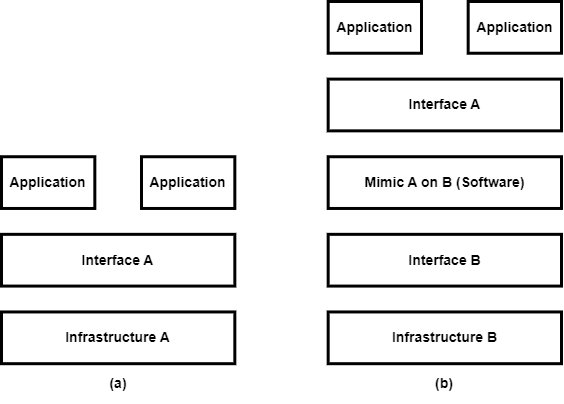
When we think of virtualization, we think of a methodology that separates our resources into different environments. The latter can have different execution environments based on the resources allocated by the users. These resources can be based on computing power, memory, disk space, and network. In virtualization, we are asking the existing interface to mimic the behaviour of another system.
Virtualization can help its users diversify the development and production environment. Based on the application, the user can decide on the operating system flavour and the libraries. Virtualization enables a high degree of flexibility and portability. Many tech giants like Amazon Web Services (AWS) and Azure offer virtual machines (VMs), and users can host their applications on these VMs. These modern-day distributed systems are called data centers and clouds. The infrastructure difference between the deployment of regular and virtualized applications can be seen in Figure 7.
Virtualization can be categorised into three types:
- Hardware virtualization (Type-1)
- Desktop virtualization (Type-2)
- Containerization (Type-3)
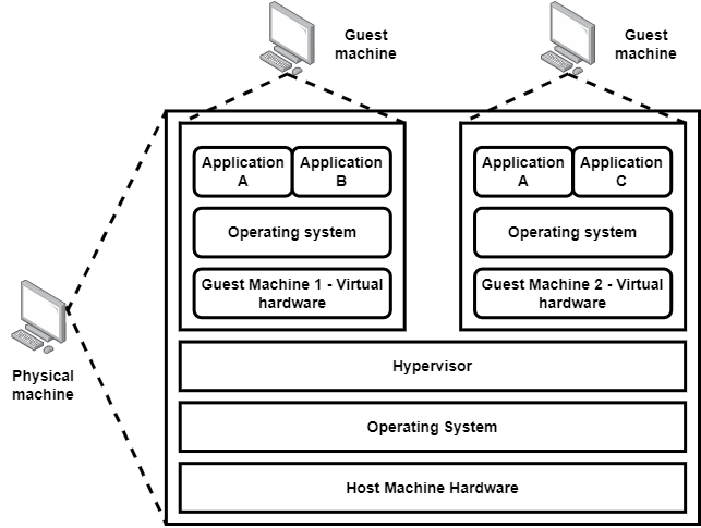
Hardware virtualization: Suppose you want to run Ubuntu on your Windows machine — sounds tricky, right? Well, it’s possible with hardware virtualization. In this sort of virtualization, we have a guest machine over the host machine. These terminologies — host and guest — are used to define a physical machine and a virtual machine, respectively. This separation of the guest machine from the host machine is done via software or firmware, known as a hypervisor.
Desktop virtualization: For hardware virtualization, we were hosting a guest machine over the host machine. But what if we want to separate the logical desktop from the hardware itself? This is where desktop virtualization comes in. When users want to interact with such a desktop setup via desktop virtualization, they first connect to a network and then use a keyboard, mouse or touchpad to connect to it. The virtualized desktop can be accessed via another machine or mobile device. The host machine in this scenario can cater to multiple virtual machines at the same instance for multiple users. With desktop virtualization, an organisation can enjoy perks like scalability and a reduction in capital expenditure.

Containerization: Containerization can be classified as OS level virtualization. It is a feature of the modern-day operating system where the kernel allows the existence of multiple isolated user-space instances of these containers. All the requests by these containers are then forwarded to the host machine’s kernel to entertain them. For the user the container may look like a real computer, but it is just another process for the host machine. The best thing about being isolated in the container is that any application or service running on it can only see the container’s contents and its attached devices assigned by the host machine. A few important containers are:
- Docker
- AWS Fargate
- Canonical LXC
- OpenVZ
- CoreOS
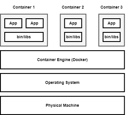
Figure 10: Containerization
In the next part of this series of articles, we will discuss containerization in detail, including container architecture, container engine, container networking, and container runtime. Till then keep exploring virtualization!


