With the embedded market being flooded with open source hardware boards, it’s tough finding one that not only suits your budget, computing power needs, etc, but is also backed by a strong community, beginner friendly documentation and a great out-of-the-box experience. The author’s search finally ended at MinnowBoard, which successfully lived up to all his expectations, from a hobbyist’s point of view.
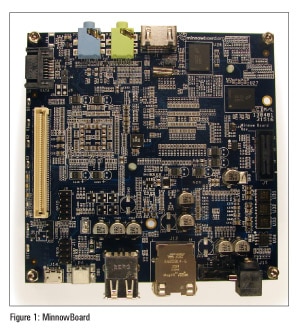
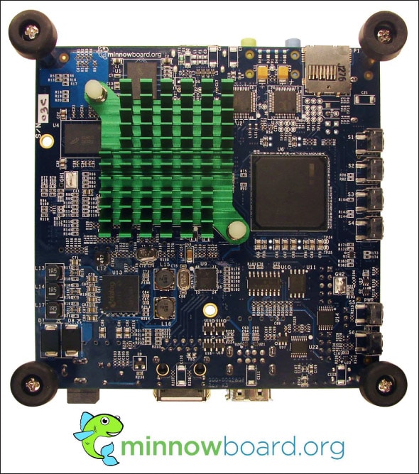
MinnowBoard (see Figure 1) is an open source hardware board based on the Intel x86 architecture. It is also a reference platform for the Yocto Project (https://www.yoctoproject.org), which lets you build your own embedded Linux distribution. MinnowBoard can be complemented with plug-in boards called ‘lures’, which augment its functionality. Listed below are some of the cool features of MinnowBoard.
Processor
- 1GHz Intel Atom E640 processor
- 1GB DDR2 RAM
Connectivity
- SPI, GPIO, I2C, CAN, SATA, SDIO, PCI Express, microSD card slot, DVI
- Gigabit Ethernet
- USB host (x2)
Software
- 4GB microSD card with embedded Linux distribution (the Angstrom OS)
Size
10.66 cm x 10.66 cm (4.2 x 4.2)
Resources
While playing around with MinnowBoard, you will have a number of doubts. The following links would be the best places to start looking for answers:
Websites:
http://www.elinux.org/Minnowboard
http://www.minnowboard.org/
IRC:
#minnowboard
Operating systems supported by MinnowBoard
At the time of writing this article, Angstrom is the officially supported operating system. Support for Android, Ubuntu and others will follow soon.

Where to buy MinnowBoard
You can buy it from various worldwide distributors such as Mouser, DigiKey, Special Computing, Element14, etc.
The cost of MinnowBoard is currently US$ 199.
MinnowBoard lures
As mentioned earlier, a lure is a plug-in board (similar in concept to the Arduino ‘shield’) used to extend the functionalities of MinnowBoard. At the time of writing this article, breakout board (aka ‘BOB’ lure), trainer lure and beacon lure were available. More are to follow soon. For more information about the lures, please refer to the following link:
http://www.elinux.org/Minnowboard:Lures_Specifications
Box contents
When you purchase a MinnowBoard, you get the following items included in the box: MinnowBoard, a USB cable, 4GB microSD card and a power adapter.
Download the latest Angstrom image
Please visit the link below to download the latest Angstrom Linux image for the MinnowBoard:
http://dominion.thruhere.net/koen/angstrom/minnow/Angstrom-development-GNOME-image-eglibc-ipk-v2012.12-minnow-2013.05.24.img.xz
At the time of writing this article, the latest image available for download was ‘Angstrom-development-GNOME-image-eglibc-ipk-v2012.12-minnow-2013.05.24.img.xz
Preparing the microSD card
For the purpose of this article, I am using Ubuntu 12.10 running on a 64 bit machine. Now insert your microSD card into the computer but make sure that it is not mounted. Now, identify the correct raw device name (like /dev/sde – not /dev/sde1). You can do this by using a tool called disk utility in Ubuntu. Now navigate to the folder where you have downloaded the image using the terminal. Type the following command into the terminal window to write the image to the microSD card:
xzcat Angstrom-development-GNOME-image-eglibc-ipk-v2012.12-minnow-2013.05.24.img.xz | sudo dcfldd of=/dev/sdX
Here, ‘sdX’ stands for the raw device ID of the microSD card. Please be patient as this operation will take some time. Once successful, remove the microSD card.
Booting MinnowBoard
Now, plug in the microSD card into the MinnowBoard. To power it up, connect the 5V/2.5A power supply to the MinnowBoard. Then, you can either choose to take the GUI or the Command Line approach. In the GUI approach, you will connect an external display to the DVI port on MinnowBoard, and the USB compatible keyboard and mouse on the corresponding USB host ports.
In the Command Line approach, connect the MinnowBoard to your computer using the USB cable provided. The next step is to setup the terminal emulator so that we can access the board’s serial console. There are two possible ways here. Either use a terminal emulator or the Linux ‘screen’ command. Let us discuss the first method. Install minicom/Gtkterm in Ubuntu. I personally prefer minicom. Install it by typing the following command in the terminal window:
sudo apt-get install minicom
Start minicom by typing the following code into the terminal:
sudo minicom -s
Configure it by selecting the correct USB port, set the baud rate to 115200, and both software and hardware control to NONE.
The other way is to use the Linux ‘screen’ command, as shown below. It’s much easier too!
screen /dev/ttyUSB1 115200
Also, in most cases, the virtual USB serial port is ttyUSB1. If it does not work, try ttyUSB0.
If all went well, you should be greeted with a familiar Angstrom login in the terminal as shown in Figure 2. The username for the same is ‘root’ and for the password, just press ‘ENTER’. You should see the following prompt:
root@minnow:~#
User LEDs on MinnowBoard
There are a total of five LEDs on MinnowBoard as shown in Figure 3. Out of those five, two are user LEDs, namely D11 and D12, but by default, they cannot be used as user LEDs. You need to change their default trigger for that.
The user LEDs are accessible via the user space in Linux at the location given below, on the filesystem:
/sys/class/leds
There is one directory per user LED, named as shown below:
/sys/class/leds/minnow_led0
/sys/class/leds/minnow_led1
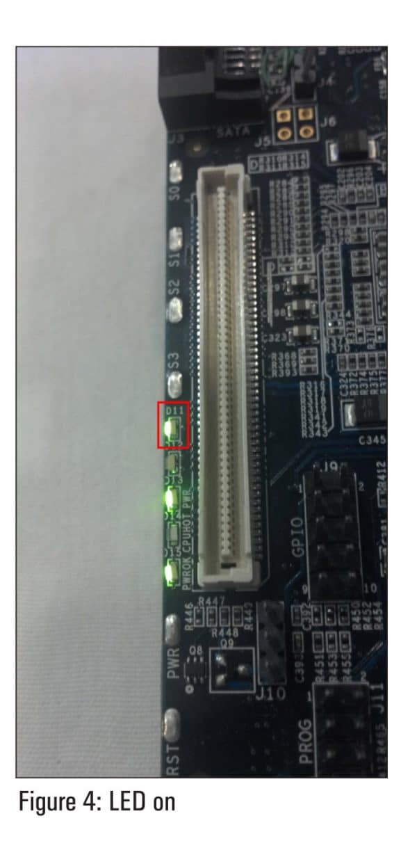
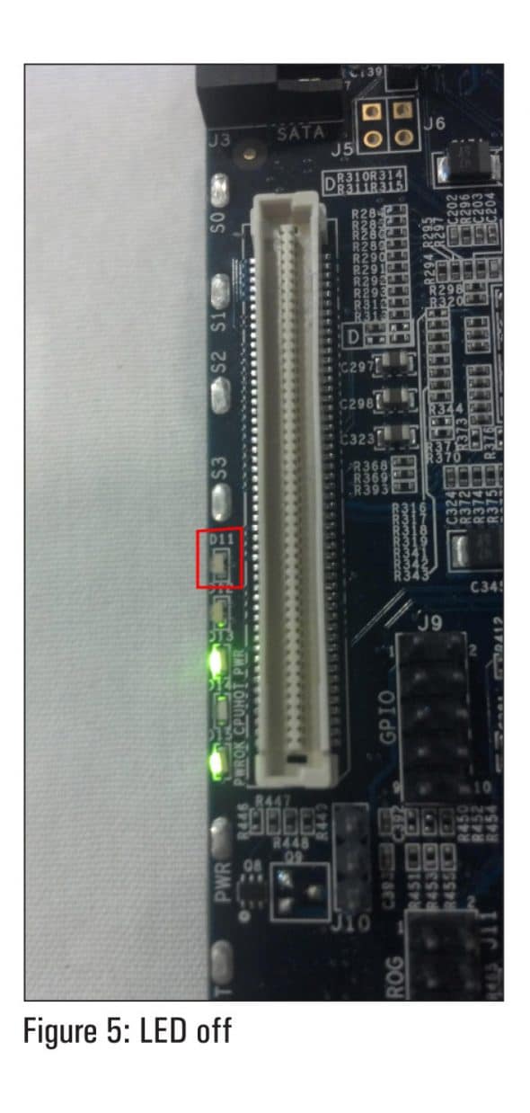
Here, led0 is D11 while led1 is D12. Inside each one of those directories, there is a file named ‘brightness’. If you write a ‘1’ or a ‘0’ to this file, then you can control the status of that LED, i.e., toggle it ON or OFF, respectively.
Changing the default trigger
In a nutshell, what we are trying to do is to access the on board user LEDs via the user space in Linux. To be more precise, we are trying to use the sysfs interface. Sysfs is a virtual filesystem, which enumerates the devices and busses attached to the system (board, in our case) into a file system hierarchy that can be accessed from user space. It is generated by the kernel and always mounted at /sys. As discussed earlier, the trigger for D11 and D12 LED(s) has to be changed to make them function as user LEDs. I would describe ‘trigger’ as the API used to link an LED to an ‘event’ in kernel space. Here, ‘event’ could be a microSD card or Ethernet activity, heartbeat, power, etc. To understand this better, let’s look at LED D11, for example. The trigger for D11 has been set by default to ‘heartbeat’. So, to use it as a user LED, we have to change the trigger for it to ‘none’ as shown below:
echo none > /sys/class/leds/minnow_led0/trigger
Toggling the user LED
This is the best part. Write the following commands in your terminal to toggle the D11 user LED (the first one is for turning ON and the latter for turning OFF):
echo 1 > /sys/class/leds/minnow_led0/brightness
echo 0 > /sys/class/leds/minnow_led0/brightness
You should get the output shown in Figures 4 and 5.
Acknowledgement
I would like to thank Scott Garman, David Anders, Dave Albert for all their help and guidance. A huge shoutout to Dave Stewart and the Yocto Project team at Intel for such an awesome initiative!


