


This article is about connecting various IoT devices on Thinger.io, an IoT platform. This step-by-step tutorial will guide you on how to connect a development board to the platform and start sending data from the device.
Devices connected by the Internet of Things (IoT) achieve higher functionality because they interface via a distributed network with numerous physical objects. They are equipped with embedded software, sensors and connectivity choices with the objective of collecting and sharing data with each other as well as with the central point through the internet. This opens the doors to various challenges in terms of data processing, storage and security. IoT platforms bridge this gap between the world of physical objects and of actionable insights.
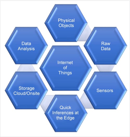
Every IoT ecosystem has its own unique set of input, processing and output elements. However, all of them have the typical flow setup shown in Figure 1, which consists of the components listed in Table 1.
| 1 | Physical objects: People, things, machines, vehicles |
| 2 | Raw data: Reading of any parameter |
| 3 | Sensors: Conversion of any physical quantity to an electrical signal |
| 4 | Quick decision at the edge: Urgent decision making through limited resources |
| 5 | Storage: Physical/cloud based choices |
| 6 | Data analysis: Study and processing of data |
An IoT platform is an on-premises software suite or a cloud service (IoT platform as a service [PaaS]) that monitors and may manage and control various types of endpoints. Open source IoT platforms are gaining popularity by blending hardware devices, APIs and online services for task management.
Thinger.io provides a scalable cloud base to connect devices. With the help of its admin console, it can be linked to a project through various boards like Raspberry Pi, Arduino, ESP8266, and Intel Edison. Open source libraries imported by the user assure scalability, security and speed through a couple of lines of code.
There are various components and applications offered on the Thinger.io menu bar. Our task for now is limited to adding a device — the first and preliminary step to start an ecosystem.
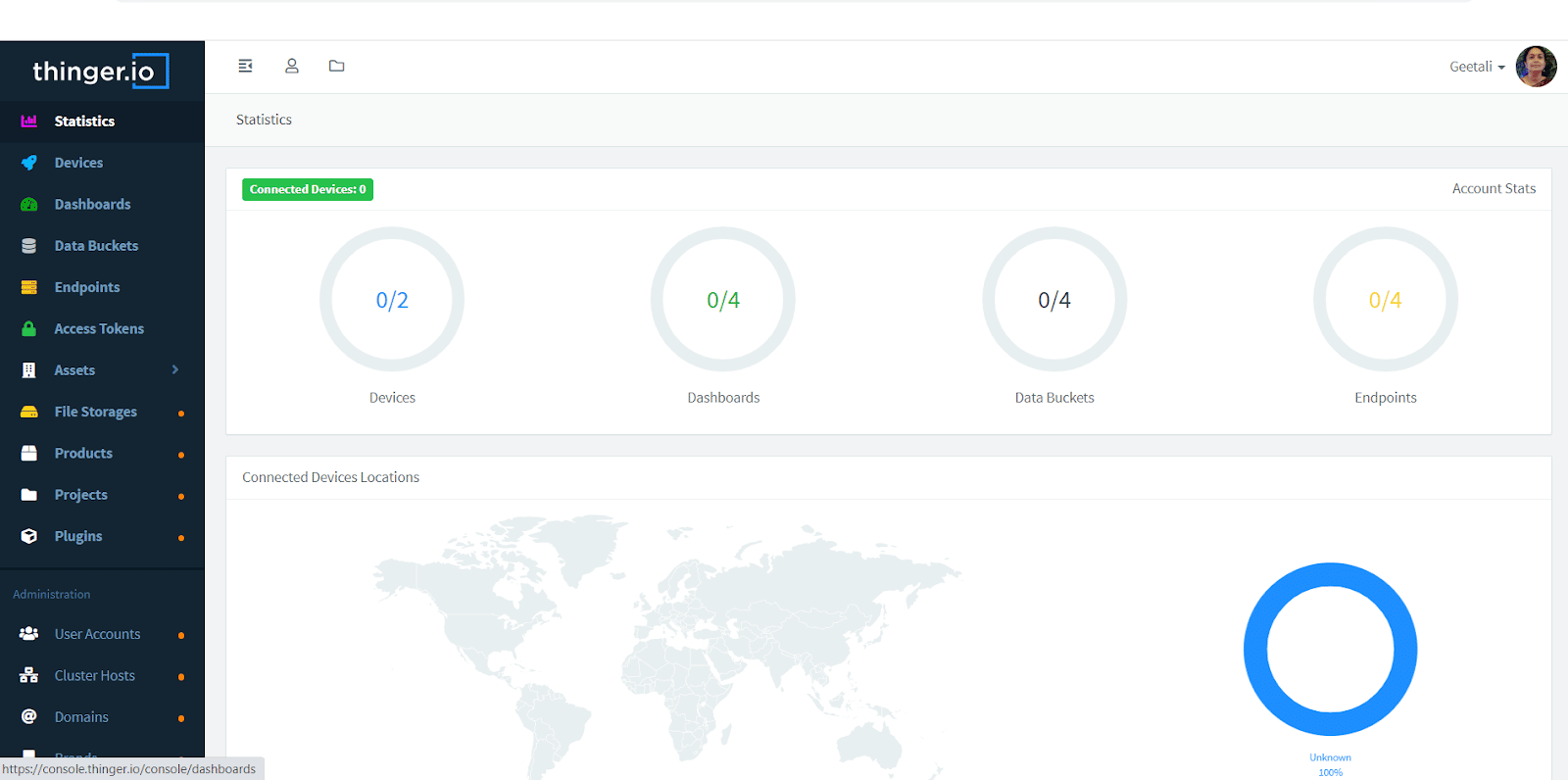
The first step involves signing up to the platform. Enter your personal details for the profile settings. Remember this also becomes your user name for all further processing on this platform. Once you have entered your profile settings, you can move on to the statistics, as shown in Figure 2.
Go to the Devices tab and create a device. This will ask for more details, as shown in Figure 3.
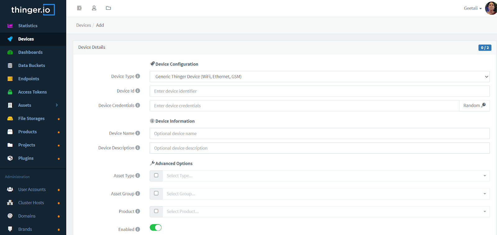
The device type is generally a generic Thinger device (Wi-Fi, Ethernet, GSM). However, the user has the option to select HTTP devices (Sigfox, Lora, cURL)/ MQTT device/NB-IoT. The Device ID is important and you have to remember it while interfacing with your code. Device information is optional and is limited to the user (for identification). But Device Credentials are vital. Each device has its own identifier/credential, so that a compromised device does not affect other devices. All your passwords in the server are stored securely using PBKDF2 SHA256 with a 32-byte salt generated with PRNG and a non-depreciable number of iterations. (Please remember, the password cannot be recalled later.)
If the steps have been implemented correctly till now, you should see your device disconnected when you press the Add Device button.
Using your new Device ID and the Device Credentials to connect the new device, you will need to install the required libraries or development environment. For the present example, we will be using the Arduino IDE along with an ESP8266 device.
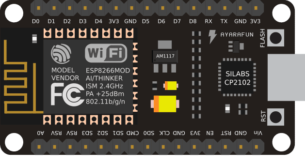
The ESP8266 chip (Figure 4) from Espressif is the new generation of low-cost Wi-Fi chips after the TI CC3000/CC3200. This small chip not only integrates the entire Wi-Fi features, but also a powerful programmable MCU. Depending on the board layout (ESP-01, ESP-03, ESP-07, ESP12, etc), it is attached to a programmable flash, ranging from 512K to 4M. This increases the available user code space, and makes possible other cool features like a small file system or OTA updates. I am using the ESP 12 module for the present illustration.
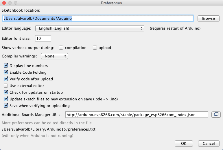
The device can be directly programmed from the Arduino IDE. The very first requirement is to install the board via the Arduino Boards Manager (Figure 5). From the File menu, go to Preferences, and enter http://arduino.esp8266.com/stable/package_esp8266com_index.json in the Additional Boards Manager URL.
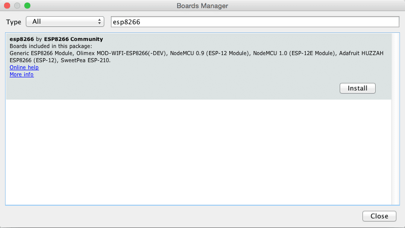
The next step involves installing the ESP8266 board. Go to Tools > Boards > Board manager. Then search and install the esp8266 package (Figure 6).
This should now enable any program involving ESP8266 directly from the Arduino IDE. By going to Tools > Boards you should see the new ESP8266 boards installed. Select your board to be able to compile code for the ESP8266.
You can find additional information for the ESP8266 package in the ESP8266 GitHub repository. The easiest board to program is the NodeMCU, which does not require pressing Flash + Reset buttons for uploading the sketch. For other boards you will need to use a USB to serial converter (3v3!) and flash the sketch by setting some GPIOs to GND.
Use the code below to connect an ESP8266 device to the cloud platform in a few lines using the Wi-Fi interface. Please remember to modify the arduino_secrets.h file with your own information.
#define THINGER_SERIAL_DEBUG
#include <ThingerESP8266.h>
#include “arduino_secrets.h”
ThingerESP8266 thing(USERNAME, DEVICE_ID, DEVICE_CREDENTIAL);

void setup() {
// open serial for monitoring
Serial.begin(115200);
// set builtin led as output
pinMode(LED_BUILTIN, OUTPUT);
// add WiFi credentials
thing.add_wifi(SSID, SSID_PASSWORD);
// digital pin control example (i.e. turning on/off a light, a relay, configuring a parameter, etc)
thing[“led”] << digitalPin(LED_BUILTIN);
// resource output example (i.e. reading a sensor value)
thing[“millis”] >> outputValue(millis());
// more details at http://docs.thinger.io/arduino/
}
void loop() {
thing.handle();
}
arduino_secrets.h
#define USERNAME “your_user_name”
#define DEVICE_ID “your_device_id”
#define DEVICE_CREDENTIAL “your_device_credential”
#define SSID “your_wifi_ssid”
#define SSID_PASSWORD “your_wifi_ssid_password”
Alternatively, install the Thinger.io custom library. Follow the path File>Examples>thinger.io>ESP8266>serial debug.
Compile and upload the code as we do for any other Arduino code. Once implemented, the inbuilt LED in the ESP8266 should glow.
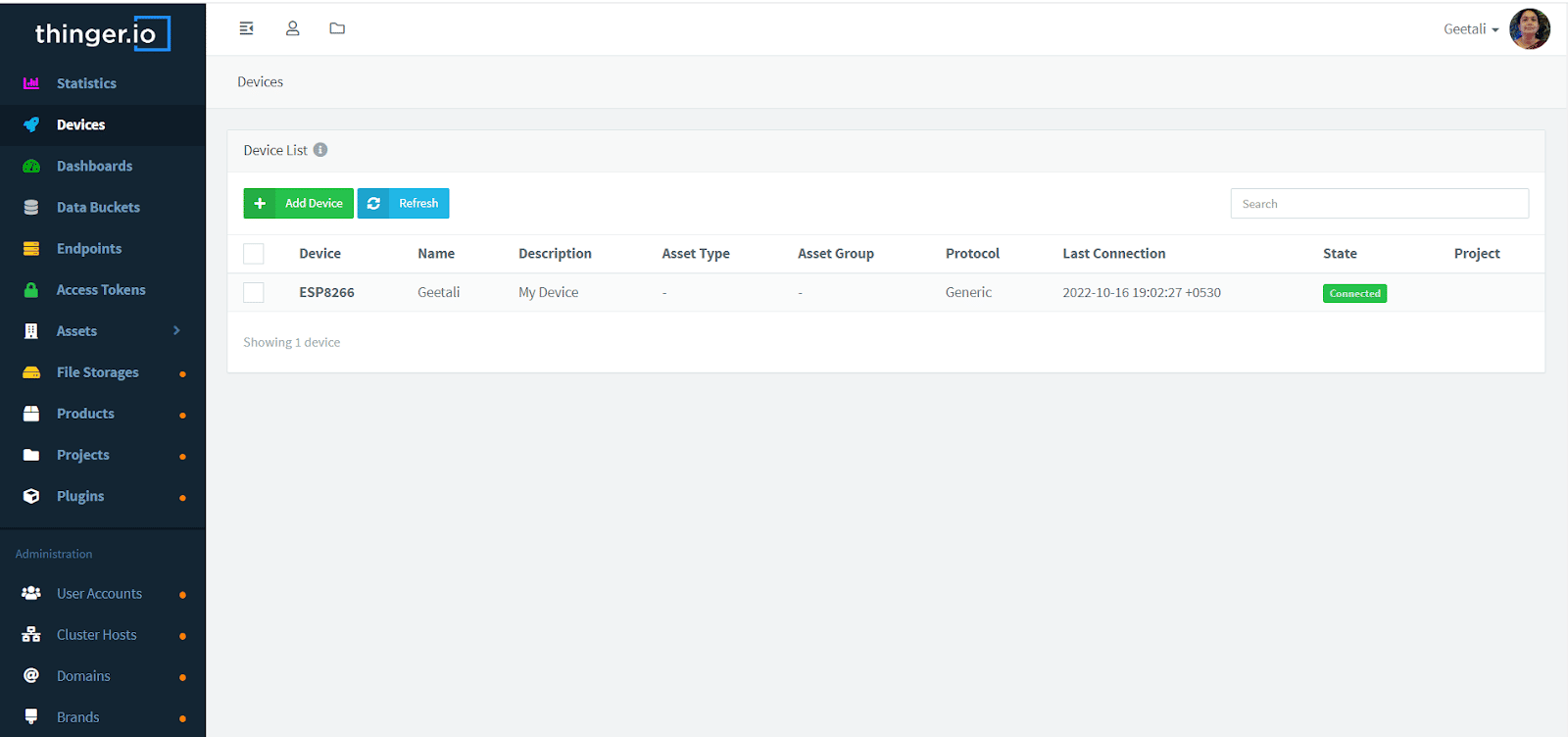
If the steps are implemented correctly, Thinger.io should show that ESP8266 has been connected (Figure 7).
We just saw how to connect ESP8266 to Thinger.io. Do follow the steps to connect it or similar development boards to try out more possibilities with the platform.


