


Breaking a complex monolith system into a set of collaborating microservices pays rich dividends in terms of auto-scaling, time-to-market and adopting modern technologies, etc, to name a few. So far, we have seen how a monolith like UMS (user management system) can be decomposed and deployed in a polyglot environment. In this twelfth and last part of the series, we take a look at the patterns that are central to the success of microservices architecture. We conclude with the final design of the UMS.
microservices are relatively small in size and easy in complexity, in comparison with monolith systems. It doesn’t mean that chopping down a complex system into smaller microservices will automatically solve the problem. There are two aspects to microservices. Decomposition is invariably one of them. The domain-driven design lays fundamental principles that govern the decomposition. The success of microservices architecture also depends on the second aspect, i.e., deployment. It deals with how these microservices are collaborated, exposed, monitored and managed.
There are quite a few patterns in the area of microservices that are popular. Tools like Dockers for containerisation and Kubernetes for orchestration implement some of these patterns. For instance, we have seen how easy it is to deploy containerised services like AddService, FindService and SearchService without worrying about draining the resources. We have also seen how Kubernetes is helpful in creating and managing the replicas of these services to scale. Let us have a look at a few more microservices patterns.
Data management patterns
In the case of UMS, we have used only one database for all the microservices. This is referred to as shared database pattern, and is not necessarily always the case. Individual microservices may maintain the data in separate databases. For instance, in an e-commerce environment, OrderService may store the orders in one database whereas InventoryService may store the product inventory in another database. This approach is called database per service pattern. This doesn’t mean that OrderService uses MySQL whereas InventoryService uses MongoDB. The separation can also be in terms of dedicated schema, dedicated tables or collections, etc. The advantage of database per service is obvious. Each service can choose the best data management suitable to its needs. A change in the data model of one service does not impact the other services.
Like in every other sphere, nothing comes for free. Database per service poses an issue at the time of processing the data that spans two services. For instance, booking an order involves OrderService and something like a WalletService. In such cases, implementing transactions based on classic ACID constraints is not practical. Though we can employ a 2-phase commit or 2PC in such cases, it leads to locking the involved databases for a longer period of time. It also hampers the ability to add and remove services over a period of time. In some cases, 2PC may not even be practical. For instance, some services may use data management techniques where the concept of committing and rolling back a transaction may not even exist. In some other cases, the participating service may be a third-party service, which we cannot lock.
The pattern named saga is used in such cases. To put it simply, a saga is a series of local transactions. Unlike in the case of 2PC, the participating services do not lock their databases beyond their local transaction. In case any local transaction that is part of a saga fails, the participating services run compensatory local transactions to restore consistency. In other words, the system may briefly become inconsistent during a saga, but eventually, the consistency is restored. For traditional data engineers, this looks odd. However, in many cases, such an eventual consistency is just good enough.
There are two popular patterns used to implement sagas. In the orchestrator pattern, an execution controller (SEC) tells each of the participating services to run a local transaction or to run a compensatory transaction. The SEC holds the current state of the saga at any point in time. This is really good for debugging, etc. In the choreography pattern, the participating services communicate among themselves to carry out the saga. This approach is good when the number of services is less.
To get the best results, saga is implemented along with two other important patterns, namely, CQRS and event sourcing.
CQRS stands for Command Query Responsibility Segregation. One set of microservices processes queries, whereas the other set processes commands like creation, updation and deletion of data. Such segregation helps in fine-tuning the respective databases for their purposes. The success of such segregation lies in how these two databases are synchronised.
If we take it a bit more forward, event sourcing patterns recommend not to mutate the database until it is really required. In this pattern, the command microservice only remembers the commands but does not execute them for as long as it is possible. This improves performance. When there is a need to really mutate the database, these command events are replayed.
There are a few more patterns in the area of data management like transactional outboxing, API composition, etc. Though many organisations still implement most of these patterns on their own, there are several open source frameworks and libraries like Eventuate available to aid the teams.
Deployment patterns
We already know that a service can be deployed on a dedicated box (service instance per host) or co-hosted on a given box (multiple instances per host). We also know that services can be deployed on VMs (service instance per VM) or on containers (service instance per container). Their merits and demerits are obvious. We used the service instance per container pattern for deploying the UMS.
There is another alternative deployment pattern called serverless. This is offered by cloud providers such as AWS. In this approach, the cloud provider offers us a ready-made run-time environment. For example, it may offer JVMs. Our only job is to build the event handling functions and register them with the environment. AWS calls these functions Lambda functions. They are known as Google Functions, Azure Functions, etc, depending on the cloud provider. For instance, we may deploy an event handling function that is invoked against a specified REST API call.
For example, on the AWS platform, we can register a Lambda written in Java, Python or any other supported languages against a REST endpoint. These functions just accept the event data and return a JSON response object. Receiving the REST request, extracting the request data, invoking the registered Lambda, and rendering the JSON response are taken care of by the AWS platform. Depending on the load, AWS takes care of running the required number of Lambda instances. This way, we do not worry about building code, containerisation, orchestration, etc. We just use the API of the provider to develop and deploy the functions. Since we are no longer involved in server creation or provisioning, etc, this model is called serverless, though there is always a server!
Serverless is more suitable for event-driven services since the billing is based on the number of function invocations, where the function is expected to be finished in the given time.
Communication patterns
We may also refer to these as collaboration patterns. There are two predominant patterns in this area.
When services interact with each other directly by invoking them, it is said to be a remote procedure invocation (RPI). In this approach, a service invokes another service by calling a published REST API endpoint. It is inherently synchronous and potentially leads to an anti-pattern called a distributed monolith. This is a scenario in which all the microservices block each other by waiting for each other synchronously.
In the other case, the services may collaborate by sending messages through a broker. This is referred to as a messaging pattern. This approach is asynchronous, highly scalable and, at the same time, a bit complicated.
In the case of UMS, we used the Kafka message broker and that’s how we want the AddService and JournalService to collaborate. Let us quickly develop the JournalService to prove this point.
UMS JournalService
This service listens to Kafka brokers, collects the messages on a specific topic and writes them to a central audit log. We are free to choose any platform to build the service, though we chose Java Spring Boot here.
First things first — make sure the pom.xml has the following dependencies:
<dependency>
    <groupId>org.springframework.boot</groupId>
    <artifactId>spring-boot-starter</artifactId>
</dependency>
<dependency>
    <groupId>org.springframework.kafka</groupId>
    <artifactId>spring-kafka</artifactId>
</dependency>
<dependency>
    <groupId>com.fasterxml.jackson.core</groupId>
    <artifactId>jackson-core</artifactId>
</dependency>
<dependency>
    <groupId>com.fasterxml.jackson.core</groupId>
    <artifactId>jackson-databind</artifactId>
</dependency>
Build a DTO that captures the user data that is added to the UMS:
import java.util.Date;
public class UserRecord {
    private String name;
    private long phone;
    private Date since;
    public UserRecord() {
    }
    public UserRecord(String name, long phone, Date since) {
        this.name = name;
        this.phone = phone;
        this.since = since;
    }
    // getters and services
}
Since Kafka only delivers the byte arrays to the consumers, our JournalService must deserialize the byte array into the UserRecord DTO to get the Java object for further processing.
import org.apache.kafka.common.serialization.Deserializer;
import com.fasterxml.jackson.databind.ObjectMapper;
public class UserDeserializer implements Deserializer<UserRecord> {
    @Override
    public UserRecord deserialize(String topic, byte[] data) {
        try {
            return new ObjectMapper().readValue(data, UserRecord.class);
        } catch (Exception e) {
            e.printStackTrace();
            return null;
        }
    }
}
Now, let us build the actual Kafka consumer. Spring Boot offers powerful annotations for Kafka integration. The JournalHandler is a Spring Bean that acts as the Kafka listener on a configured topic. Kafka delivers the same message to any number of consumers as long as they are from different consumer groups. To be compatible with this requirement, the JournalHandler is configured with a specific group-id as well. Even when multiple instances of the JournalHandler are deployed and subscribed to Kafka, none of them receives duplicate messages, thanks to Kafka.
import org.springframework.beans.factory.annotation.Autowired;
import org.springframework.kafka.annotation.KafkaListener;
import org.springframework.stereotype.Component;
@Component
public class JournalHandler {
    @Autowired
    private JournalAdapter adapter;
    @KafkaListener(topics = “${ums.user.add.topic}”, groupId = “${ums.user.add.consumer}”)
    public void handle(UserRecord user) {
        adapter.record(user.toString());
    }
}
Going by the design in Part 3 of this series, we are supposed to use a hypothetical third-party library named FileJournal to write the messages into the audit log. Recollect that we employed the adapter pattern to build a protection layer. Thus, the JournalHandler is wired with JournalAdapter. But, since the FileJournal is not guaranteed to be a Spring Bean, we need to register it with the Spring context for the adapter to pick it up. The following configuration does this:
import org.springframework.context.annotation.Bean;
import org.springframework.context.annotation.Configuration;
import com.glarimy.lib.FileJournal;
@Configuration
public class UserJournalCofiguration {
    @Bean
    public FileJournal getFileJournal() throws Exception {
        return new FileJournal();
    }
}
Not every microservice needs to be a REST endpoint. In fact, we see more and more event-driven microservices these days. The JournalService is one such event-driven microservice. The following bootstrap is sufficient:
import org.springframework.boot.SpringApplication;
import org.springframework.boot.autoconfigure.SpringBootApplication;
@SpringBootApplication
public class UserJournalService {
    public static void main(String[] args) {
        SpringApplication.run(UserJournalService.class, args);
    }
}
The last step is to inject the configuration through application.properties:
spring.kafka.bootstrap-servers=kafka:9092
spring.kafka.consumer.auto-offset-reset=earliest
spring.kafka.consumer.key-deserializer=org.apache.kafka.common.serialization.StringDeserializer
spring.kafka.consumer.value-deserializer=com.glarimy.ums.app.UserDeserializer
ums.user.add.topic=com.glarimy.ums.user.add
ums.user.add.consumer=ums-consumer
Essentially, this configuration declares the topic on which the JournalService listens, the consumer group it belongs to, the deserializers it uses for extracting the keys and values and, of course, the Kafka broker it listens to.
The Dockerfile is simple:
FROM maven:3.5-jdk-8 AS build
COPY src /usr/glarimy/src
COPY pom.xml /usr/glarimy
RUN mvn -f /usr/glarimy/pom.xml clean package -DskipTests
ENTRYPOINT [“java”,”-jar”,”/usr/glarimy/target/ums-journal-service.jar”]
Build the container image with the following command:
docker build -t glarimy/ums-journal-service.
And the following command publishes the image on the Docker hub:
docker push glarimy/ums-journal-service
Since the JournalService is not a user-facing service via REST API or any other means, we are not required to register it as a Kubernetes service. A simple deployment will work:
apiVersion: apps/v1
kind: Deployment
metadata:
  name: ums-journal-service
  labels:
    app: ums-journal-service
spec:
  replicas: 1
  selector:
    matchLabels:
      app: ums-journal-service
  template:
    metadata:
      labels:
        app: ums-journal-service
    spec:
      containers:
        - name: ums-journal-service
          image: glarimy/ums-journal-service
Create a new deployment on top of the other deployments we made earlier.
kubectl create -f <deployment-file-name.yml>
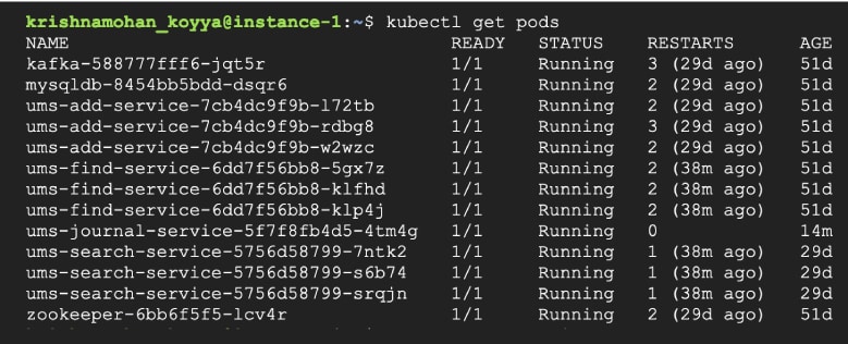
Check the pods in the cluster. It looks something like what’s shown in Figure 1. You can observe that Kafka, MySQL, AddService, FindService, SearchService and JournalService have their pods running on the cluster.
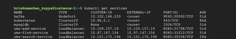
A quick look at the service listing gives us the IP addresses exposed within the cluster, as in Figure 2. For example, the AddService is available on 10.109.157.19:8080.
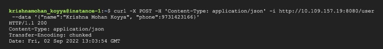
Make a REST call using any suitable client like cURL to add a new user to the UMS. An example is given below:
curl -X POST -H ‘Content-Type: application/json’ -i http://10.109.157.19:8080/user --data ‘{“name”:”Krishna Mohan Koyya”, “phone”:9731423166}’
This call goes well, as shown in Figure 3.
Now, let us check if the audits.log is updated with the newly added user. For that, we need to get into the pod on which the JournalService is running. From Figure 1, we know the pod-id. It is ums-journal-service-5f7f8fb4d5-4tm4g.
Use the following command to get into the pod:
kubectl exec -it ums-journal-service-5f7f8fb4d5-4tm4g – bash
Once the prompt is available, use the following command to peek into the audits.log:
The result will be similar to Figure 4.

We can now celebrate our accomplishments. We are able to deploy a few desperate microservices, scale them individually, and make them collaborate. This is not trivial.
At the same time, it is not sufficient also.
As long as the end user is also on the same Kubernetes cluster, the UMS is available for adding, finding or searching the users. In other words, the end users should be on the same network of the cluster in the data centre. You will agree with me that this doesn’t make any sense!
The end users are always on a public network. They cannot and should not be on the data centre network. So, how is the end user able to access the UMS?
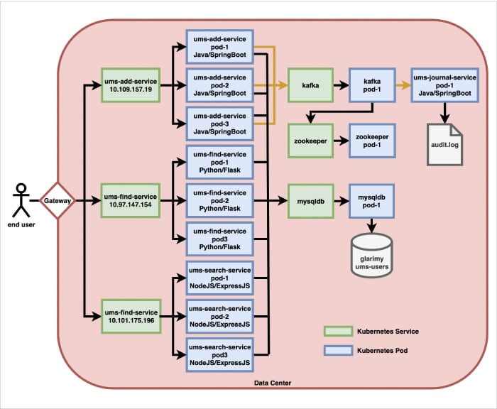
This is where the API gateway pattern plays an important role. A gateway acts as the entry point into the microservice infrastructure. It runs on a public IP address so that the end users can connect to it. The gateway, upon receiving the requests from the end users, needs to delegate them to the appropriate microservices.
Figure 5 shows what such a setup looks like.
But how do you build such a gateway? Well, in most of the cases you will use third-party ready-to-use gateway solutions like Kong, etc. The non-trivial gateways offer a lot of other features besides simple request delegation. They do filtering, throttling, protocol-conversion, security, and a lot of other things.
And other patterns
Before closing, let us also have a look at a few other microservices patterns.
Service discovery is one such pattern. Entities like gateway and others are required to discover the service instances that are deployed on the cluster. A service registry is used to maintain the data of all the services at a central location. Service may be registered in two different ways: 1) The service itself registers with the service registry. This is called the self-registration pattern; 2) The deployer registers the service. This is called the registrar pattern. In either case, once the service is registered, others will be able to discover it.
And the last set of patterns we deal with falls under the observability aspect. Unless there is a mechanism to know the health of the services and the state of the requests, it is impossible to guarantee reliability. Many platforms offer distributed tracing, aggregated logs, application metrics, etc, to aid observability.
Epilogue
To sum up, the microservices architecture has been well-tried and well-documented since it captured the imagination of the industry about a decade ago. A designer with a grasp of the patterns (ranging from basic object-oriented patterns, domain-driven patterns, messaging patterns, and distributed patterns to microservices patterns) and a hand on a few tools that implement these patterns is well positioned to architect web-scale mission-critical applications.
In this Design Odyssey series, we covered some nuances of designing modern applications over 12 parts. Though we used a simple user management system to illustrate some critical patterns, a good understanding of these concepts and patterns is sufficient even when dealing with a complex system.
The code base of the series is available at https://bitbucket.org/glarimy/the-design-odyssey.
A list of references and other resources will also be added when this series takes the form of a book.


