


In the first part of this article (carried in the previous issue of OSFY), we discussed the step-by-step procedure of OpenStack installation with Tacker. This second part gives an overview of virtualised network functions and how they can be deployed on the OpenStack platform. It also explores the concept of service function chaining (SFC) and how it can be used to string together multiple VNFs to create a service chain.
As cloud computing continues to gain momentum, the use of virtualised network functions (VNFs) is becoming increasingly popular. With VNFs, software implementations of network functions can be deployed on virtual machines instead of proprietary hardware devices, providing greater flexibility and scalability.
Moving from traditional networking to software defined networking (SDN)
In traditional networking, network devices such as routers and switches are used to forward traffic between different networks and devices. These devices are typically dedicated hardware appliances that are configured with specific rules and settings to control the flow of traffic. Traditional networking architectures rely on a hierarchical structure, with devices at the edge of the network connecting to devices at the core of the network. Traffic is forwarded between these devices using a variety of protocols, such as TCP/IP and Ethernet.
Traditional networking is widely used in a variety of environments, including enterprise networks, service provider networks, and the internet. It is a reliable and well-established technology that has been in use for many years. However, traditional networking can be inflexible and can be difficult to modify or update, particularly in large and complex networks. As a result, newer technologies such as software defined networking (SDN) and network functions virtualisation (NFV) have been developed to enable more flexible and agile networking.
Software defined networking: SDN is an approach to networking that frees administrators from having to manually configure each network device by allowing them to define and manage network policies and behaviours using software. In SDN design, the network is defined and managed by a central controller, while networking components (such as switches and routers) just serve as simple forwarding elements that execute the controller’s commands.
One of the main advantages of SDN is that it enables network administrators to respond to fluctuations in network requirements more rapidly and easily. Making modifications to individual devices can be time-consuming and error-prone with standard networking techniques, especially in large networks. With SDN, managers may modify the network using the central controller, which can be done more quickly and with fewer chances of error.
SDN also gives the network more adaptability and programmability. Administrators can utilise software to develop unique policies and behaviours that are tailored to the requirements of their company because the central controller is in charge of defining the behaviour of the network. This can facilitate the support of new apps and services while also enhancing network performance and efficiency.
SDN, in its entirety, signifies a change in how networks are planned and operated, shifting the attention away from individual devices and towards the network. It provides many advantages, such as increased productivity, adaptability, and programmability, which can assist organisations in better meeting the changing needs of their users and company.
Control plane and forwarding plane: The control plane and the forwarding plane (data plane), which are two distinct operational planes, collaborate to manage and route traffic via a network in an SDN architecture. The functionality of the network is managed and controlled by the control plane. It accomplishes this through communication with the central controller, the key element of the SDN architecture. The central controller is a piece of software that controls the network’s policies and behaviours. It runs on a server or other specific device.
On the other side, the forwarding plane is in charge of actually moving traffic through the network. It accomplishes this by following the guidelines and directives established by the control plane. The forwarding plane is made up of networking components like switches and routers, which act as straightforward forwarding elements and execute commands from the central controller. The control plane and the forwarding plane in an SDN architecture are decoupled, which means they work separately from one another. This can help to increase the effectiveness and performance of the network by allowing the control plane to concentrate on controlling the network and the forwarding plane to concentrate on forwarding traffic. To govern and route traffic via the network, the control plane and the forwarding plane are two essential parts of SDN architecture.
The forwarding plane oversees forwarding traffic based on the network’s policies and behaviours, whereas the control plane is in charge of setting those policies and behaviours. The SDN architecture is detailed at https://doi.org/10.1109 INDISCON54605.2022.9862876.
Network functions virtualisation: Network functions virtualisation (NFV) allows network functions such as firewalls, load balancers, and VPNs to be implemented in software and run on standard hardware instead of specialised equipment. This technology is often used in conjunction with software defined networking (SDN). Virtualised network functions or VNFs are created through software implementation and operate on conventional hardware servers. Virtual switches route traffic to and from the VNFs, and the management plane oversees and controls the network and VNFs, including monitoring performance, troubleshooting, and data collection.
NFV provides several benefits, including faster and easier installation and scalability of network functions, as well as greater flexibility and adaptability. VNFs are easily programmable and portable, which can facilitate changes to the network based on evolving needs.
Tacker: VNF life cycle management in OpenStack
Tacker is an open source project that is part of the OpenStack cloud computing platform. Its purpose is to simplify the deployment and maintenance of network functions virtualisation (NFV) in OpenStack setups. With NFV technology, network services such as firewalls, load balancers, and VPNs can be implemented in software and operated on common hardware rather than on specialised networking equipment. Tacker is a suite of tools and APIs that enable administrators to create and manage VNFs and their connections, streamlining the deployment and maintenance of NFV services in OpenStack systems.
Tacker is designed as a service that runs on the OpenStack cloud and is accessible through a web-based dashboard or command line interface. Resources needed to enable VNFs, such as virtual machines and switches, are automatically provisioned, and administrators can define VNFs and their connections using a declarative paradigm. Overall, Tacker is a valuable tool for organisations adopting OpenStack that want to leverage NFV, providing a range of tools and APIs that facilitate the deployment and administration of VNFs in OpenStack environments, thereby enhancing the network’s flexibility and programmability.
The complete Tacker architecture is available on this link.
Deploying a VNF in OpenStack
By deploying VNFs in OpenStack, organisations can enhance network agility, reduce hardware costs, and rapidly scale and adapt their network services.
VNF descriptor: A virtual network function (VNF) descriptor is a document or file that outlines the characteristics and behaviour of a virtualised network function. These VNFs are software versions of network functions like load balancers, firewalls, and VPNs that can run on standard hardware instead of specialised networking equipment. The VNF descriptor includes information about the VNF’s capabilities, such as input and output parameters, supported protocols, and other relevant details. Typically, the VNF descriptor is defined in a standard format like OpenStack TOSCA, making it easy for VNF management tools to process and understand. It is important to note that TOSCA is a standard developed by OASIS (Organisation for the Advancement of Structured Information Standards) that provides a language for describing cloud services and their relationships, as well as an API for managing those services.
In NFV systems, VNF descriptors automate the deployment and maintenance of VNFs. They allow administrators to declaratively specify the characteristics and behaviours of VNFs, enabling the automation of resource provisioning and VNF configuration. The sample VNFD file is seen in Figure 1.
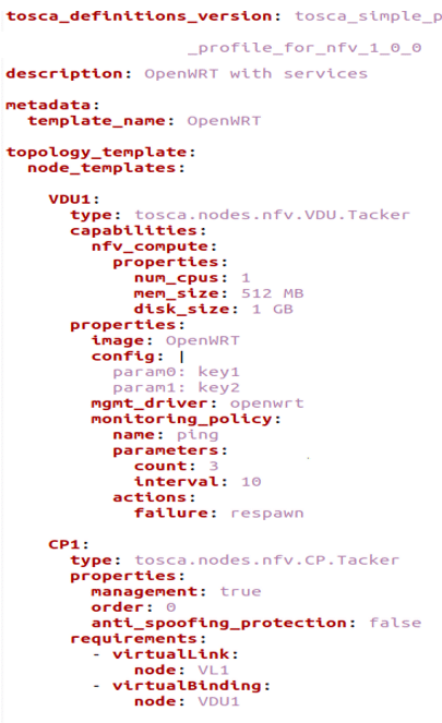
The VNFD (virtual network function descriptor) provides a detailed description of VNFs, which are categorised into three basic node types: virtual deployment unit (VDU), connection point (CP), and virtual links (VL).
A VDU specifies the virtual machine (VM) instance that will host the VNF, including its monitoring policies, the image that will be used, and the flavour. It is similar to Nova servers in OpenStack.
The CP represents the virtual network interface card (NIC), which is virtually connected to a VDU. It is also known as single root I/O virtualisation (SR-IOV) NIC. This node type provides information about the logical virtual link object that connects VDUs, and it corresponds to Neutron ports in OpenStack.
Lastly, the VL node type provides details about the logical virtual link object that connects VDUs, like Nova networks in OpenStack. It describes the connections between VDUs and can be used to specify network policies, such as bandwidth or quality of service (QoS) requirements. The VNFD’s standard format, such as the OpenStack TOSCA format, enables administrators to easily automate the deployment and configuration of VNFs in NFV environments.
Steps for VNF deployment in OpenStack
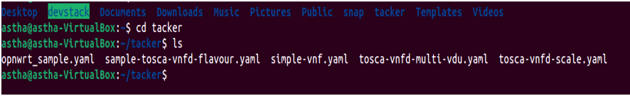
Step 1: To ensure proper organisation of Tosca templates, it is recommended to create a separate folder named ‘tacker’ that will hold all the templates related to Tacker. This will make it easier for administrators to locate and manage these templates. Figure 2 shows an example of how the folder structure may look.
Step 2: Launch OpenStack on the browser.
Step 3: We need to create a network topology to be able to attach VNF to the desired network which is present under the network tab.
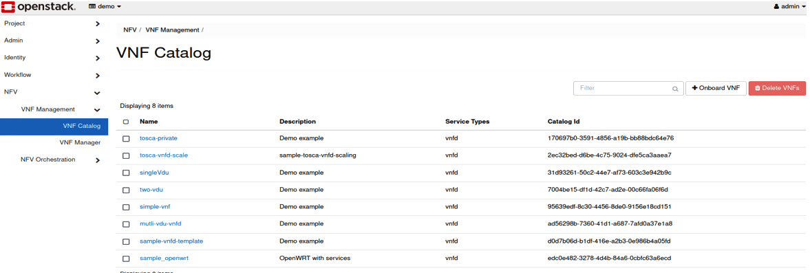
Step 4: To instantiate a VNF, we first need to load the corresponding TOSCA template to the VNF catalogue. Figure 3 shows the VNF catalogue interface, where the ‘Name’ tab displays the list of VNF templates that have been uploaded. Each template is assigned a unique catalogue ID and can be given a user-defined description and service type. The ‘Onboard VNF’ button allows the user to upload a new VNF template to the catalogue.
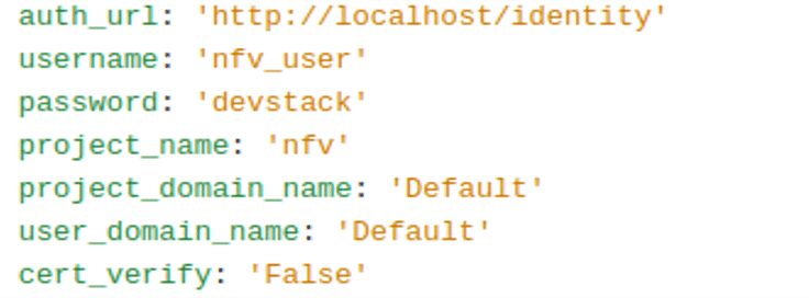
Step 5: We need to create a virtual infrastructure for VNF deployment. For that, we need to create a vim_conf.yaml file with the properties shown in Figure 4.
Step 6: Once the vim_conf.yaml is ready, one needs to create a virtual infrastructure manager (VIM) with OpenStack using the following command:
$ openstack vim register --description ‘OpenStack vim’ -- config-file vim_config.yaml Site1
This command will be used to register a VIM, which requires a configuration file. In our case, this is vim_config.yaml via the OpenStack command and the –description tag is used to describe the VIM that will be created in Site 1.
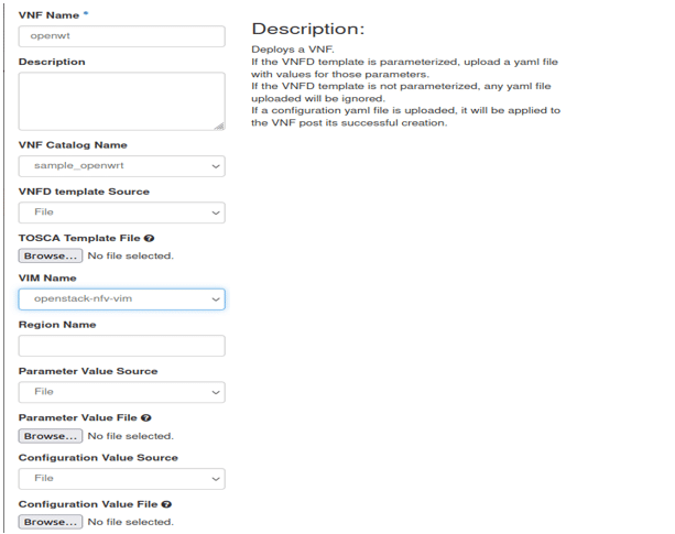
Step 7: We are now ready to instantiate a TOSCA template by giving a name to the VNF, the template to be used, and the name of the VIM that we created now. Figure 5 shows the VNF deployment.
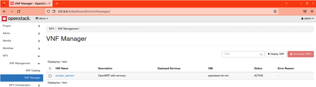
Step 8: Deploy the VNF and once successful it will look like what’s shown in Figure 6.
One can check the details of the launched VNF by selecting the VDU detail tab.
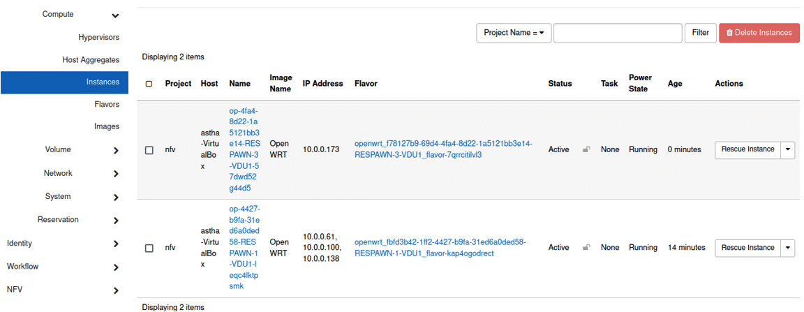
Step 9: One just needs to click on the desired instance to be able to interact with it. The instance will be visible in the console. Figure 7 shows the project, the name of the VNF, the flavour used, and whether the instance is running or shut down.
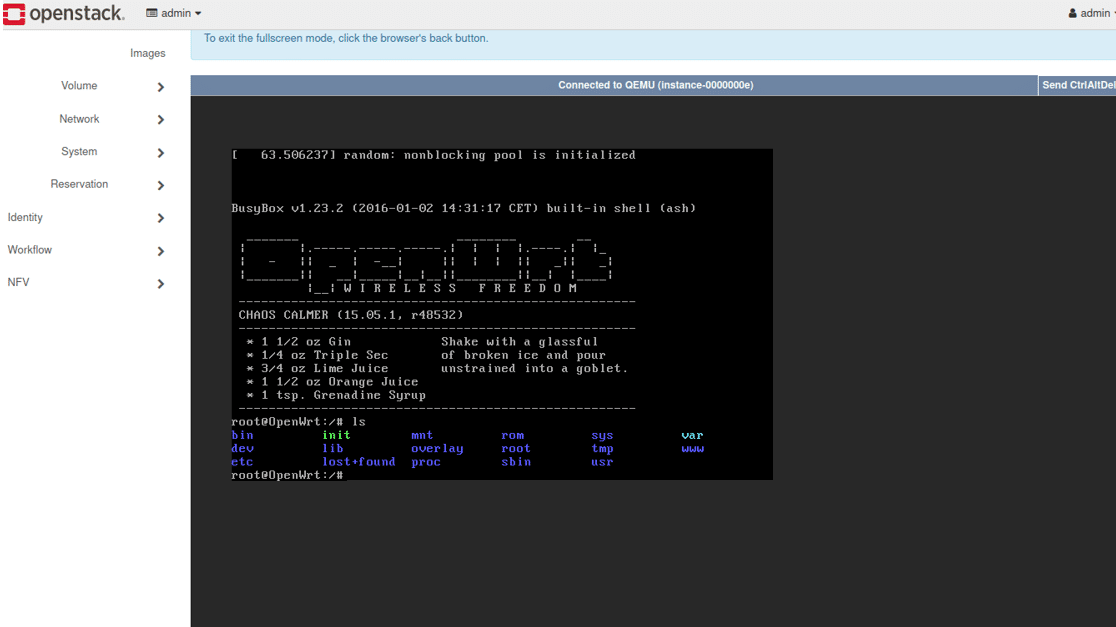
A sample of the launched instance is shown in Figure 8.
Service function chaining (SFC): A feature of SDN
Traditionally, network configurations have hard-coded the routing of traffic through network services like load balancers and switches. This means that network managers must manually adjust the devices and interfaces to change the way traffic is routed through the network, making it difficult to adapt the network to changing requirements quickly. To address this issue, OpenStack has introduced service function chaining (SFC), which is essentially the software defined networking (SDN) version of policy-based routing (PBR).
SFC allows network managers to specify the order in which network functions, such as load balancers, firewalls, and VPNs, should be applied to incoming traffic. This approach is commonly used in NFV setups, where network operations are performed in software and run on standard hardware. With SFC, administrators can define a series of network operations that should be applied to incoming traffic, ensuring that traffic is routed through its intended paths.
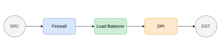
For example, in an SFC configuration, inbound traffic can be routed through a firewall for security screening before being directed to a load balancer to be distributed among multiple servers. The traffic is then passed through these processes in the appropriate order, enhancing the network’s flexibility and programmability. The sequence of VNFs connecting the source and destination can be seen in Figure 9.
The VNFGD, or virtual network function graph descriptor, is a document or file that describes the dependencies and connections between various VNFs in a network. VNFs are software versions of network functions like load balancers, firewalls, and VPNs that can run on regular hardware. The VNFGD typically uses a standard format like OpenStack TOSCA, making it easy for VNF management tools to read and process.
In an NFV system, VNFGDs are used to automate VNF deployment and management by enabling administrators to declaratively describe the dependencies and relationships between VNFs. This facilitates the provisioning of resources and configuration of VNFs through automation. VNFGDs are an essential component of the NFV ecosystem as they provide a mechanism to specify VNF dependencies and interactions in a standardised manner.
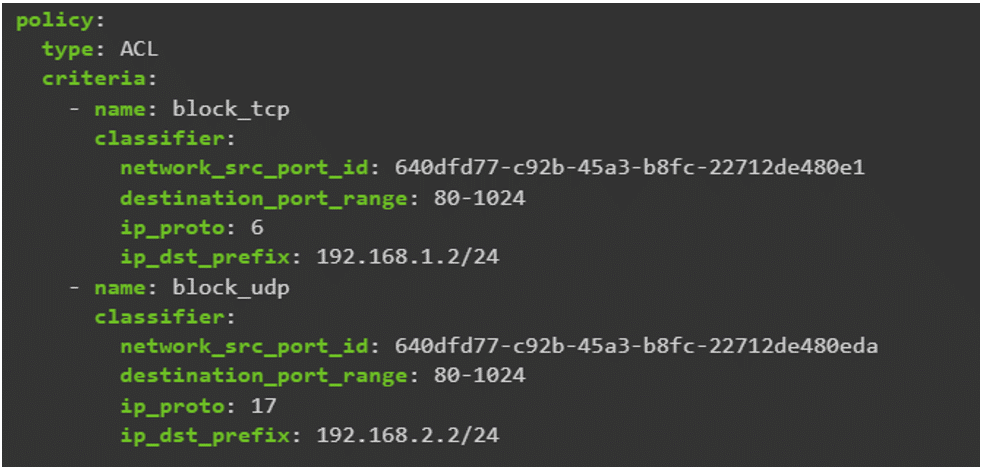
By using VNFGDs, administrators can define and control VNFs with ease through automation tools, increasing network programmability and flexibility. Figure 10 shows a sample VNF graph template where two rules based on IP address are used to either block a TCP packet or a UDP packet.
Steps for SFC deployment in OpenStack
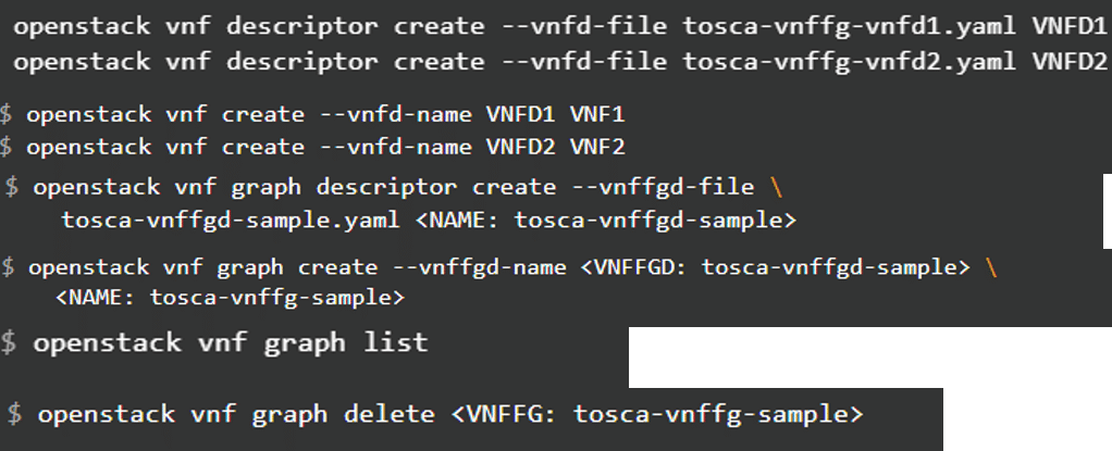
Step 1: First, onboard VNF templates from the Tosca template, give a name to them and then launch them.
Step 2: Now create a descriptor for the VNF forwarding graph, and then launch the graph.
Step 3: List and show the VNF graph deployed.
Step 4: Delete the VNF graph deployed.
The commands to deploy the above-mentioned steps in OpenStack are shown in Figure 11.
We hope this article will be a valuable resource for those looking to understand the basics of VNF deployment on OpenStack, and how it can be used to create powerful and flexible network services using service function chaining.


