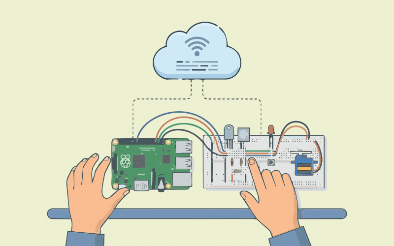
The Raspberry PI Pico board is excellent for building a range of IoTbased
applications.
Our IoT journey started with the basics of the Raspberry Pi in an article published in the January 2025 edition of OSFY (https://www.opensourceforu.com/2025/02/ raspberry-pi-pico-the-wonder-board-for-iot-applications/). Let’s move further on this journey by using more tools and external sensors that interface with the Pi Pico boards.
Command line tools
For the command line and automation Ninjas, the MicroPython project provides tools like pyboard and mpremote to interact with the RPI Pico boards. We’ll experiment with both to drive these boards through their respective Docker containers. A Dockerfile_Pyboard and execute command is given below:
docker build -f Dockerfile_Pyboard -t pyboard to create
pyboard docker image.
FROM python:3.14-alpine
SHELL [“/bin/ash”, “-o”, “pipefail”, “-c”]
WORKDIR /tmp
RUN wget https://github.com/micropython/micropython/archive/
refs/heads/master.zip \
&& unzip master.zip \
&& cp micropython-master/tools/pyboard.py /usr/local/bin/
pyboard \
&& rm -rf master.zip micropython-master \
&& pip install pyserial \
&& mkdir /etc/rpipico
WORKDIR /etc/rpipico
ENTRYPOINT [“pyboard”]
CMD [“-h”]
If you execute the command:
docker run --rm --device=/dev/ttyACM0:/dev/ttyACM0 pyboard
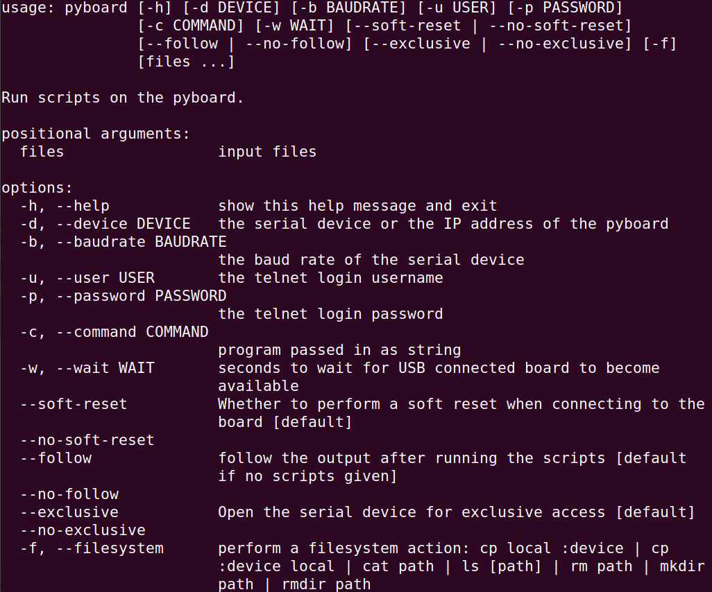
…it dumps a help screen to show all that you can do with
it, as shown in Figure 1. Please ensure you are not connected
to your RPI Pico board through Thonny, and then execute the
following command:
docker run --rm --device=/dev/ttyACM0:/dev/ttyACM0 pyboard -c
‘from machine import Pin;from time import sleep;p=Pin(“LED”,
Pin.OUT);p.toggle();sleep(3);p.toggle()’
…to witness the onboard LED light up for a few seconds before it turns off. The pyboard is a nice tool to experiment with running a few MicroPython one-liners on your RPI Pico boards in a non-interactive mode. It can also run MicroPython code from source file(s). Let’s run tgleobled.py through the following command:
docker run -it --rm --device=/dev/ttyACM0:/dev/ttyACM0 -v
${PWD}/tgleobled.py:/etc/rpipico/tgleobled.py:ro pyboard
tgleobled.py
You can also upgrade the RPI Pico board MicroPython firmware through pyboard and the local command line, without pressing the BOOTSEL button and plugging the micro-USB physical actions. To upgrade the MicroPython firmware to the latest version, execute the command:
wget -r --tries=10 “https://micropython.org/$(curl -s
https://micropython.org/download/RPI_PICO/|grep ‘\.uf2’|head
-1|grep RPI|awk -F ‘”’ ‘{print $2}’)” -o log -O /tmp/RPI_
PICO-Latest.uf2
…to download the latest firmware for your RPI Pico board. Now execute the command:
docker run --rm --device=/dev/ttyACM0:/dev/ttyACM0 pyboard -c
‘import machine;machine.bootloader()’
…to put your board in the bootloader mode mounted as a local directory on your computer. The next command is:
cp /tmp/RPI_PICO-Latest.uf2 $(mount|grep RPI|awk ‘{print
$3}’)
This copies the latest downloaded firmware to the board. Once the new firmware is programmed, the device will automatically reset and be ready for use. This way you can fully automate the RPI Pico board firmware upgrade and quick testing. Isn’t it amazing?
Let’s now explore the next command line tool mpremote, which has way more features than pyboard. Execute the following command:
docker build . -f Dockerfile_Mpremote -t mpremote
…to create the Docker image:
--- Start of Dockerfile_Mpremote ---
FROM python:3.14-alpine
SHELL [“/bin/ash”, “-o”, “pipefail”, “-c”]
WORKDIR /tmp
RUN wget https://github.com/micropython/micropython/archive/
refs/heads/master.zip \
&& unzip master.zip \
&& cp -r micropython-master/tools/mpremote /usr/local/bin/
\
&& rm -rf master.zip micropython-master \
&& pip install -r /usr/local/bin/mpremote/requirements.txt
\
&& ln -s /usr/local/bin/mpremote/mpremote.py /usr/local/
bin/mpr \
&& mkdir /etc/rpipico
WORKDIR /etc/rpipico
ENTRYPOINT [“mpr”]
CMD [“--help”]
--- End of Dockerfile_Mpremote ---
Now execute the command:
docker run --rm --device=/dev/ttyACM0:/dev/ttyACM0 mpremote
This brings up a help screen to show all that you can do with it. You can use the exec command to run any code contained in a passed string like we did through the pyboard.
Use the run command to execute a local MicroPython code. You can execute the command:
docker run -it --rm --device=/dev/ttyACM0:/dev/ttyACM0
mpremote repl
…to launch an interactive shell running the MicroPython board. This provides many shortcuts to accomplish several common tasks for your board. You can also interact with multiple boards plugged into your desktop:
docker run -it --rm --device=/dev/ttyACM0:/dev/ttyACM0
--device=/dev/ttyACM0:/dev/ttyACM1 mpremote devs
…to list the available serial ports. In fact, you can do a lot using it on the command line. Do explore the mpremote through its official documentation link provided in the Reference section. Going forward, with pyboard and mpremore, there will be no further dependency on an IDE to play with and program your Pico boards.
Real-world applications of PI Pico
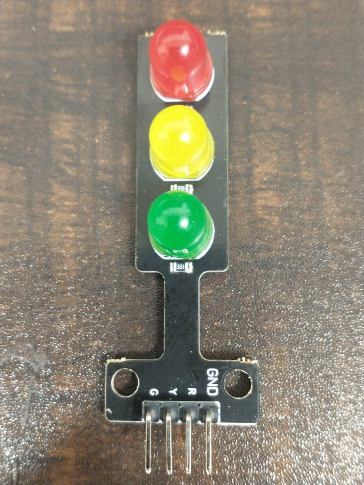
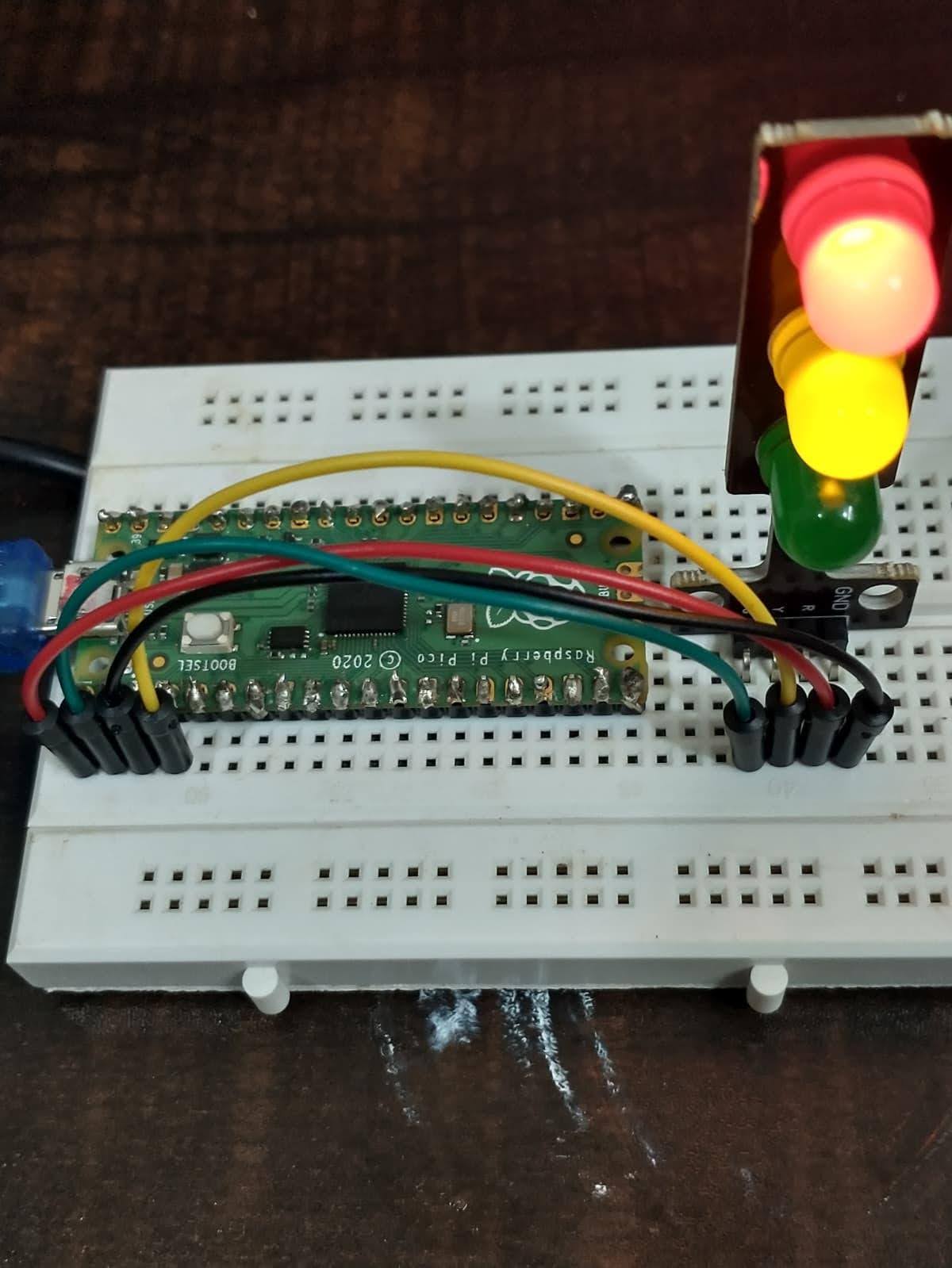
Let’s start with the traffic light module shown in Figure 2. Figure 3 shows the wired circuit of the external LED traffic lights. The logic of the code is simple: configure 3 GPIO pins (choose from GPIO pin numbers in the board diagram) for driving the different colours of external LEDs, ensuring the red, amber, and green sequence is on, respectively, with a delay in between.
--- Start of trafficlight.py ---
from machine import Pin, reset
from time import sleep
tfl1 = {}
tfl1[‘rled’] = Pin(0, Pin.OUT) # R, GPIO 0, Pico Pin 1
tfl1[‘gled’] = Pin(1, Pin.OUT) # G, GPIO 1, Pico Pin 2
tfl1[‘yled’] = Pin(2, Pin.OUT) # Y, GPIO 2, Pico Pin 4
# G, GND,
Pico Pin 3
def rstlds(tfl):
tfl[‘rled’].off()
tfl[‘gled’].off()
tfl[‘yled’].off()
def stoponred(tfl):
tfl[‘rled’].on()
tfl[‘gled’].off()
tfl[‘yled’].off()
def gongrn(tfl):

tfl[‘rled’].off()
tfl[‘gled’].on()
tfl[‘yled’].off()
def readyonylw(tfl):
tfl[‘rled’].off()
tfl[‘gled’].off()
tfl[‘yled’].on()
def readybgrn(tfl):
tfl[‘gled’].off()
tfl[‘yled’].on()

while True:
try:
stoponred(tfl1)
sleep(5)
readybgrn(tfl1)
sleep(2)
gongrn(tfl1)
sleep(5)
readybgrn(tfl1)
sleep(2)
except KeyboardInterrupt as e:
rstlds(tfl1)
reset()

--- End of trafficlight.py ---
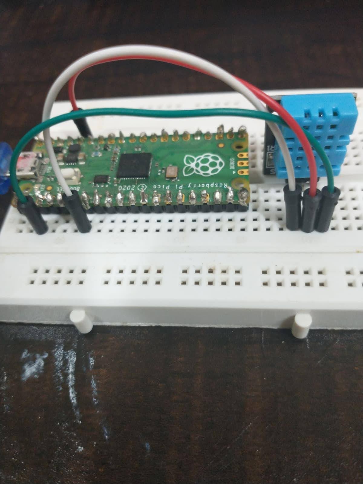
Next, see how to interface with an external sensor for capturing real-time temperature and humidity. We’ll use an inexpensive DHT 11 sensor for that. MicroPython already includes a module to handle these sensors out-of-the-box. First, assemble the connections as shown in Figure 4 and execute the code given below to read the sensor output (marked as S on the sensor) through GPIO 5 Pico pin 7 (‘-ʼ marked on the sensor connected to Pico pin 3 GND and middle VCC to pin 36 3V3(OUT)):
--- Start of dht11temphmdt.py ---
import time
import machine
import dht
sensor_pin = machine.Pin(5)
sensor = dht.DHT11(sensor_pin)
print(“ Starting DHT11 sensor readings...”)
print(“ Press Ctrl+C to stop\n”)
while True:
try:
# DHT11 needs at least 2 seconds between readings
time.sleep(2)

# Trigger a measurement
sensor.measure()
# Read the values
temp = sensor.temperature()
hum = sensor.humidity()
# Print formatted output
print(f” Temperature: {temp}°C , Humidity: {hum}%”)

except Exception as e:
print(f”Read error: {e}”)
# DHT11 Blue Case Sensor: S => Output, - => GND,
middle => 3V3
print(“Check your wiring!\n”)
--- End of dht11temphmdt.py ---
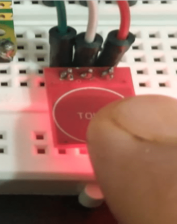
This should dump the surrounding atmospheric temperature and humidity on your terminal. Just blow your breath into the sensor and you’ll be able to see the difference in humidity values. You can also trigger other outputs like driving different colour LEDs based on different temperature ranges, switching external devices like fans on or off, etc, based on your needs and creativity.The next sensor you can interface with your board is the inexpensive TTP 223. This touch sensor outputs a high signal when you bring your finger near it and a low signal when the finger is away. It can also be used as a latch, toggling output at every touch to switch external devices on or off. Wire the TTP 223 to your board as shown in Figure 5 and execute the code given below to read the sensor output (marked as I/O on the sensor) through GPIO 5 Pico pin 7 (GND marked on sensor connected to Pico pin 3 GND and VCC to pin 36 3V3(OUT)) and, accordingly, turn on an external red-green-blue LED pattern:
--- Start of ttp223tchctrl.py ---
from machine import Pin
from time import sleep
touch = Pin(5, Pin.IN)
rled = Pin(0, Pin.OUT)

gled = Pin(1, Pin.OUT)
bled = Pin(3, Pin.OUT)
i = 0
while True:
if i > 2:
i = 0
if i == 0:
rled.value(touch.value())
gled.off()
bled.off()
elif i == 1:
gled.value(touch.value())
rled.off()
bled.off()
elif i == 2:
bled.value(touch.value())
rled.off()
gled.off()
i += 1
sleep(0.5)

www.OpenSourceForU.com | OPEN SOURCE FOR YOU | JUNE 2026 | 95
Let's Try Open Guru
gled = Pin(1, Pin.OUT)
bled = Pin(3, Pin.OUT)
i = 0
while True:
if i > 2:
i = 0
if i == 0:
rled.value(touch.value())
gled.off()
bled.off()
elif i == 1:
gled.value(touch.value())
rled.off()
bled.off()
elif i == 2:
bled.value(touch.value())
rled.off()
gled.off()
i += 1
sleep(0.5)

--- End of ttp223tchctrl.py ---
The TTP 223 sensor has an inbuilt red LED, which glows when the I/O goes high the moment your finger is near it. This way you can differentiate a faulty sensor from a working one. The sensor has two jumpers marked A and B. If you short jumper B using some solder tin, the sensor works as a latch in toggle mode. You bring your finger near it and the output stays high, then you touch it again to make it low till the next touch, and so on.
Before moving to our next useful sensor, let me introduce another electronics module that will help you reap great benefits from your Pico board. 5V relay modules are devices (magnetic switches) that can switch high voltage or high current devices on and off using a 5V signal from a Pico board. They can be used to control devices such as lights, fans, motors, solenoids, etc. The 5V relay has three high voltage terminals (NC, C, and NO), which connect to the device you want to control. The other side has three low voltage pins (ground, Vcc, and signal) which connect to the Pico board. Using a relay in your projects is super easy — just browse the internet for basics and you’re done.
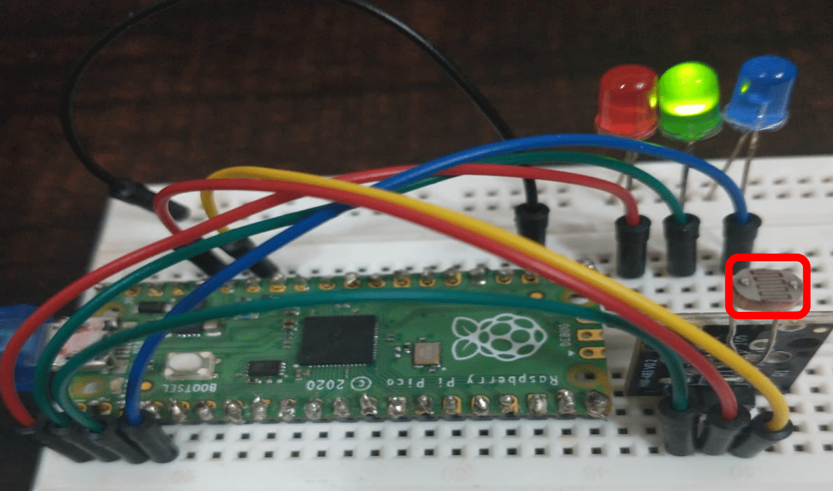
Let’s now move to interfacing the next sensor, which is a photosensor. We’ll use an analog photosensor to sense voltage inversely proportional to the amount of light falling upon it. Wire the photosensor to your board as shown in Figure 6, and execute the code shown below to read the fluctuating voltage value (marked by S on the sensor) using the analog to digital converter from GPIO 28 Pico Pin 34. The ‘- ’ marked on the sensor is connected to Pico pin 3 GND and the middle VCC to pin 36 3V3(OUT). Based on the light intensity calculated we are turning on an external red/green/blue LED indicating a range. Just try to cover the photoresistor with your finger or cover it fully with folded paper and you’ll see a different colour LED turning on. Use a relay module instead of an LED, and you have a light-controlled switch to automatically turn on/off your home equipment:
from machine import ADC, Pin
from time import sleep
photoPIN = 28
rled = Pin(0, Pin.OUT)
gled = Pin(1, Pin.OUT)
bled = Pin(2, Pin.OUT)
def rledon(rled,gled,bled):
rled.on()
gled.off()
bled.off()
def gledon(rled,gled,bled):
rled.off()
gled.on()
bled.off()

def bledon(rled,gled,bled):
rled.off()
gled.off()
bled.on()
def aledoff(rled,gled,bled):
rled.off()
gled.off()
bled.off()
def readLight(photoGP):
photoRes = ADC(Pin(28))
light = photoRes.read_u16()
light = round(light/65535*100,2)
return light

while True:
try:
lgtper = 100.00 - readLight(photoPIN)
print(“light: “ + str(lgtper) +”%”)
if lgtper < 10.00:
rledon(rled,gled,bled)

elif lgtper >= 10.00 and lgtper < 80.00:
bledon(rled,gled,bled)
else:
gledon(rled,gled,bled)
sleep(1)
except:
aledoff(rled,gled,bled)
machine.reset()
Running a web server with PI Pico
As mentioned earlier, Pico 1/2 series boards are available with wireless capabilities too. We’ll explore Pico W networking with simple programs to get you started and apply the same concepts to Pico 2W as well. We’ll use the board as an access point, without the need for a separate router and Wi-Fi network, to run an independent web server that obeys our commands. To begin, add the latest Pico W MicroPython firmware to the board. Then run the code given below, where you can turn the onboard LEDs on or off using web URLs. Running the code will dump an IP address to access your Pico web server. Just connect to the RPICOWAP Wi-Fi network and execute:
curl <ip of pico webserver>/light/on
curl <ip of pico webserver>/light/off
…to turn the onboard LED on and off, respectively.
import network
import time
import socket
from machine import Pin
from time import sleep
led = Pin(“LED”, Pin.OUT, value=0)
html = “””<!DOCTYPE html>
<html>
<head> <title>RPico W</title> </head>
<body> <h1>RPico W</h1>
<p>%s</p>
</body>
</html>
“””
def ap_mode(ssid, password, html, led):
ap = network.WLAN(network.AP_IF)
ap.config(essid=ssid, password=password)
ap.active(True)
while not ap.active():
print(‘Waiting for AP Mode Activation...’)
led.on()
sleep(0.5)
led.off()
sleep(0.5)
led.off()
print(‘AP Mode Is Active, You can Now Connect’)
print(‘IP Address To Connect to:: ‘ + ap.ifconfig()[0])

s = socket.socket(socket.AF_INET, socket.SOCK_STREAM)
s.bind((‘’, 80))
s.listen(5)
while True:
try:
conn, addr = s.accept()
print(‘Got a connection from %s’ % str(addr))
request = conn.recv(1024)
print(‘Content = %s’ % str(request))
response = html
request = str(request)
led_on = request.find(‘/light/on’)
led_off = request.find(‘/light/off’)
print( ‘led on = ‘ + str(led_on))
print( ‘led off = ‘ + str(led_off))

stateis = ‘’
if led_on == 6:
print(“led on”)
led.on()
stateis = “LED is ON”
if led_off == 6:
print(“led off”)
led.off()
stateis = “LED is OFF”

response = html % stateis
conn.send(‘HTTP/1.0 200 OK\r\nContent-type: text/html\
r\n\r\n’)
conn.send(response)
conn.close()
except OSError as e:
conn.close()
print(‘connection closed’)
ap_mode(‘RPICOWAP’,
‘SWEETRPI’,
html,
led)
You can also run your Pico board in a LAN networking mode in case you have set up a 2.4G Wi-Fi network. The code diff given below indicates the changes you need to incorporate in the picoapobled.py for running in the Wi-Fi LAN mode, also known as the station mode. Just execute the code after the changes, connect to your Wi-Fi network and make calls like done earlier to turn the onboard LED on/off.
Start of diff for picowsmobled.py
18,24c18,26
< def ap_mode(ssid, password, html, led):
< ap = network.WLAN(network.AP_IF)
< ap.config(essid=ssid, password=password)
< ap.active(True)
<
< while not ap.active():
< print(‘Waiting for AP Mode Activation...’)
---
> def lan_mode(ssid, password, html, led):
> wlan = network.WLAN()
> wlan.active(True)
> if not wlan.isconnected():
> print(‘connecting to network...’)
> wlan.connect(ssid, password)
>
> while not wlan.isconnected():
> print(‘Waiting for connection...’)
28a31
> print(‘network config:’, wlan.ipconfig(‘addr4’))
30,32c33
< print(‘AP Mode Is Active, You can Now Connect’)
< print(‘IP Address To Connect to:: ‘ + ap.ifconfig()[0])
<
---
>
72,73c73,74
< ap_mode(‘RPICOWAP’,
< ‘SWEETRPI’,
---
> lan_mode(‘Wifi Id’,
> ‘Wifi Password’,
In fact, you can turn any of the Pico examples given in the last section to get served over a wireless network, with a few changes only.
Let’s quickly incorporate the internal temperature readings to be served over the Wi-Fi LAN. A few code lines have been changed in the diff given below to access the temperature reading over the wireless network. Just run the code changes, connect to the network, and access the page (auto refreshing every 5 sec) in your browser by typing the shown IP. Isn’t it a cakewalk now for you to use various sensors and control or access their data over the network?
--- Start of diff for picowitemp.py ---
8a9
>
11c12
< <head> <title>RPico W</title> </head>
---
> <head> <title>RPico W</title> <meta httpequiv=”
refresh” content=”5”> </head>
13c14
< <p>%s</p>
---
> <p>Internal Sensor Temperature : %s</p>
18c19,29
< def lan_mode(ssid, password, html, led):
---
> def getitemp():
> sensor_temp = machine.ADC(4)
> conversion_factor = 3.3 / (65535)
> reading = sensor_temp.read_u16() * conversion_factor
> # The temperature sensor measures the Vbe voltage of a
biased bipolar diode, connected to the fifth ADC channel
> # Typically, Vbe = 0.706V at 27 degrees C, with a slope
of -1.721mV (0.001721) per degree.
> temperature = 27 - (reading - 0.706)/0.001721
> time.sleep(2)
> return temperature
>
> def lan_mode(ssid, password, html):
45,61d55
<
< request = str(request)
< led_on = request.find(‘/light/on’)
< led_off = request.find(‘/light/off’)
< print( ‘led on = ‘ + str(led_on))
< print( ‘led off = ‘ + str(led_off))
<
< stateis = ‘’
< if led_on == 6:
< print(“led on”)
< led.on()
< stateis = “LED is ON”
<
< if led_off == 6:
< print(“led off”)
< led.off()
< stateis = “LED is OFF”
63c57
< response = html % stateis
---
> response = html % getitemp()
75,76c69
< html,
< led)
\ No newline at end of file
---
> html)
\ No newline at end of file
--- End of diff for picowitemp.py ---
Although there are tons of sensors available for the Pico boards, I selected the ones that are inexpensive, easy to understand, and can be set up to become productive right away, helping initiate home automation with simple and short code chunks. I have just scratched the surface of the great IoT capabilities provided by the RPI Pico boards. A vast array of real-world projects is available freely on the internet. Do explore these.