


In its simplest avatar, a key-value database stores data as a collection of key-value pairs, with the key serving as the unique identifier for a value. Both the keys and values could be anything from simple objects to complex objects. This article centres around building a large scale key-value storage in the cloud.
A key-value store is a type of NoSQL database where each item is a combination of keys and values. A value can be stored and retrieved by referencing its key. Key-value stores are great for use cases where large amounts of data need to be stored and no complex queries have to be performed during retrieval of data. Examples include storing multimedia, cache management, real-time recommendations and advertising, hierarchical data, event log processing, etc.
Relational databases are not suitable for such use cases as they have limitations like static schema, expensive vertical scaling which is also possible up to a certain limit, only read scalability, single point of failure, and inability to consume data in large volumes. A key-value store helps to overcome these limitations.
This article presents the design and implementation of a scalable, distributed, key-value store based on the design of Pastry (http://rowstron.azurewebsites.net/PAST/pastry.pdf) and Tapestry. The application design is completely decentralised and self-adaptable to the failure of nodes in the application’s network, the exit of existing nodes and arrival of new nodes. A message is consistently routed to the relevant live nodes in the application’s network, while all nodes are connected through the Internet.
The application’s design, which is proposed in this article, can be used as a base for building various peer-to-peer (P2P) applications. Routing and location of messages is performed at the application level. The ‘Design Consistent Hashing and CAP Theorem’ (https://en.wikipedia.org/wiki/CAP_theorem) forms the foundation for the design of this application. The distributed hash tables that form a building block for P2P applications are alternatively used to make it decentralised.
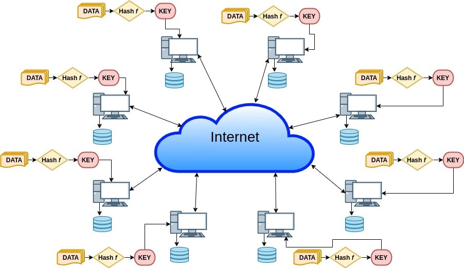
Figure 1 gives an overview of the application. Here, multiple nodes share identical responsibilities with symmetric communication between them through the Internet.
Each node performs routing, storage and retrieval of values associated with keys. Each node acts as a server as well as a client having its own space for storing key-value pairs. To understand this project, prior knowledge of Design Consistent Hashing is needed (http://www.allthingsdistributed.com/2007/10/amazons_dynamo.html).
Key-value store
A key-value store mainly performs two operations — put(key,value) and get(key) for storing and retrieving a value. A simpler version of key-value store (single server) can be a hash table implemented in any language to store key-value pairs. This will have limitations of performance and memory constraints.
The idea of Design Consistent Hashing is used to build a distributed key-value store where multiple servers are mapped on a ring. Given a message with a key, it’s routed to a live node with a nodeId nearest to the key. There is still a centralisation, which is the load distributor that stores the ring and routes the message to the corresponding server, and is also involved in reorganisation of data during a node failure.
The same idea of Consistent Hashing for a distributed table forms the building block for a peer-to-peer application, which in turn can be used as a decentralised distributed hash table.
A P2P system is a distributed system having identical capabilities and responsibilities for all nodes connected to each other through the Internet. The designed application has the following features:
- A unique nodeId is assigned to each node.
- When supplied with a message and a key, a node performs routing of the message efficiently among all live nodes to the node with nodeId closest to the key.
- A message takes an expected O(log N) steps to reach its destination node, where N is the count of live nodes in the network.
- It takes the network locality into account to optimise the distance that a message travels according to a proximity (count of nearby hops a ping request travels through to reach a live node).
Design
Each node in the application’s network is any computer system connected to the Internet running the application’s node. Each node acts as a server as well as a client. A node interacts with other live nodes in the network and responds to client requests. Each node stores information about neighbours adjacent to it in the nodeId space. It also notifies the application about the arrival and departure of nodes in the adjacent nodeId space.
Each node is assigned a nodeId, which is the md5 hash value of its IPv4 address plus port. The nodeId specifies the position of the node in a circular nodeId space. In a network on N nodes it can take up to ceil(log2^bN) steps for a message to reach its destination node.
We will look at the routing procedure and self-organisation in detail after a walk-through of the node state.
The application’s architecture has the following key classes:
- Database – It follows a singleton design pattern to store all the information relevant to a node like routing tables, neighbourhood sets, etc. The C++ STL (standard template library) provides locks used for mutual exclusion, implementing fine-grained locking. nodeId related information is stored inside the Node class object.
- LogHandler – A singleton class, which is used to write all the logs — from the running thread to the log files (LogError/LogMsg).
- Printer – This class is specified to display informative messages on the console.
- NetworkInterface – This class performs read/write operations from the network, i.e., an interface between the application and network, using UNIX provided network system calls.
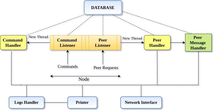
Figure 2 depicts the architecture of each node in the application. There are four key classes and separate handlers for user commands and communication between nodes in the application’s network. Command Listener handles user requests, whereas Peer Handler listens for the messages that define the contracts for communication between nodes.
Besides the key classes, Command Handler listens to the user requests and creates a new thread for the corresponding action to be taken, whereas the Peer Handler listens for requests from other nodes in the network and calls for the corresponding method as a new thread. A few sets of messages have been specified that determine which remote procedure will get invoked. Hence, these messages serve as API endpoints for our application.
The implementation uses Protocol Buffers for message serialisation (encoding) and deserialisation (decoding). Listed below are the messages used to define the interface in the application:
JoinMe – Upon the arrival of a new node in the network, send this to all adjacent nodes to update their network information.
Join – Like any other message, this message gets routed by the node that receives the new node’s joining request.
RoutingUpdate – Existing nodes send this message to the newly joined ones. This information is used by newly joined nodes to set up their routing tables and other network information.
AllStateUpdate – Propagate updates to all entries of nodes in the current node’s routing table.
AddToHashTable – To add key-value pairs to the present node.
SetValue – Store key-value pair.
GetValue – Get the value of the given key, and route it to the source that requested the value.
DeleteNode – Remove an entry for a node from the routing tables.
Shutdown – Shutdown the entire network, making all nodes exit.
Let us go through the details of the node to understand the working procedure of the application’s routing of messages and the self-organisation used for responding to the arrival, failure and departure of nodes in the network.
Figure 3 depicts the state of an application’s node, listing the critical information required by a node.
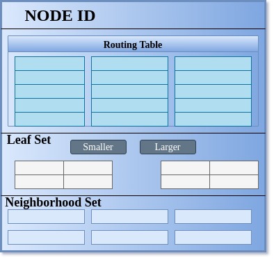
Each node maintains a leaf set, a neighbourhood set and a routing table. A node has to have a routing table maintaining ceil(log2^bN) rows with 2b -1 entries in each row, where b is a configurable parameter that we have used as 4 in our case in order to consider the key as a number in the hexadecimal system.
Hence, we will be doing our routing operation in the hexadecimal system on the 128-bit value key, which we get as 32 hexadecimal characters of the md5 digest and IPv4 plus port for nodeId. These 2b -1 entries at the nth row in the routing table refer to a node within the application’s network, whose nodeId shares an n-length prefix with the current node’s nodeId and its (n+1)th digit (hexadecimal character) is different from the present node’s nodeId. The idea is a bit similar to the way the network id for an IP is decided while routing in a network. Here, it uses bitwise AND of IP with a subnet mask, and goes for the node with a longer run of 1’s in case of a clash.
Similarly, choose the routing mechanism for a message associated with a key based upon its key value. The neighbourhood set is intended to store IP addresses and nodeIds for M closest nodes to the present node according to proximity. The leaf set L is a set of nodes with L/2 nodes having nodeId smaller than the present node’s nodeId in the nodeId space, and are the closest such nodes in this space. Similarly, there are L/2 nodes with nodeIds greater than the present node’s nodeId.
Routing of a message for the destination node happens as per the algorithm described below.
Routing algorithm (route to destination node)
- Initially, we check if the desired node lies within the range of leaf sets.
- If yes, then in a single step we can reach the destination.
- Say, ‘n’ is the common prefix length shared by the key and current node. And ‘j’ is the nth value in messages’ key.
- Check for a not NULL entry in the nth row and jth column.
- Route to the existing entry if not NULL.
- Take the union of all tables (R U M U L) and route to the most appropriate node.
To do a repair of the node’s state, the following algorithm is used.
Repair algorithm
- Leaf Set Repair
- For the smaller nodeIds that lie in the left leaf set, request the leftmost leaf node for its leaf sets. Search for an entry with nodeId less than the leftmost leaf in the request leaf set. If found, insert it into the left leaf set.
- If such an entry cannot be found, then repeat the same procedure for the second leftmost leaf node and so on until an appropriate entry is found.
- Repeat the same procedure for the right leaf set, except that the rightmost leaf node will be requested first, and then move one step left if the relevant entry is not found.
- Neighbourhood Set Repair
- Request the neighbourhood set from the rearmost neighbour of the present node. If a new entry is found, then insert it into the neighbourhood set. Otherwise, head forward repeating the same process with the node next to the previously selected node.
- Routing Table Update
- To repair R[n][j], request for the R[n][j] entries from nodes R[p][j] for all j!=i.
- When the desired entries are not found, then it goes on following the same procedure with the next row.
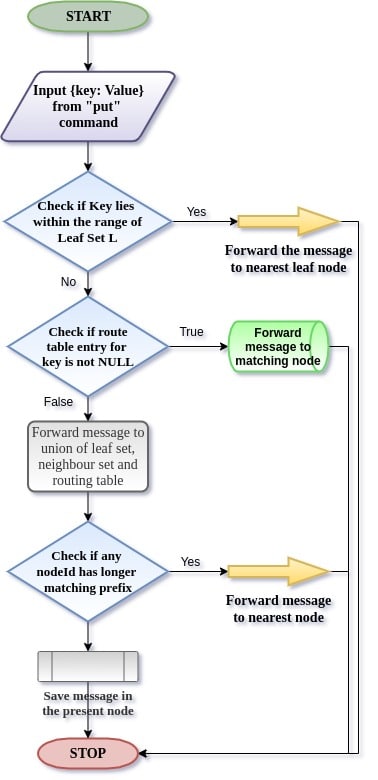
In Figure 4, a flow diagram demonstrates the working of the routing algorithm for values based on their keys involving three crucial stages of decision making.
When a new node X asks to join the application’s network to an existing node A, a special message ‘join’ with X’s nodeId is routed to the numerically closest live nodes like any other message. All nodes encountered during routing send their state information to node X as a response to the join request. In case of a node departure, the failed node within the leaf set is replaced. Every stored data is replicated across three different nodes.
Upon joining, a new node is provided with the data relevant to it, while routing. Routing table entries are fixed when an unavailable node is detected while routing. This is commented as ‘Lazy repair’ in the code. Every 30 seconds a timely leaf set repair is done. When a node quits the network, a replica of its data is created before it exits the network. This is done in response to the ‘quit’ command.
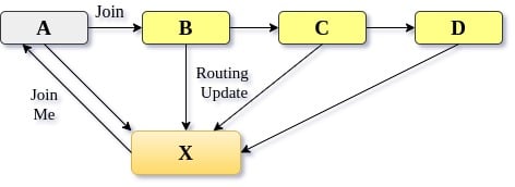
Figure 5 relates to the arrival of a new node in the existing network of nodes. New node X sends a joinMe request to the pre-existing node, which in turn publishes a join message to its neighbour nodes. All these nodes that receive a join message send their routing table to the newly joined node. New node X uses this information to populate its routing table and leaf set.
Installation
The following steps will guide you in installing and running the application’s node on any POSIX-compliant operating system. All of the code associated with the application is written in C++. Hence, a G++ compiler is required for successful installation of the application.
We have used protocol buffers to define a uniform interface for intercommunication between nodes. Install protocol buffers as described in the source repository at https://github.com/protocolbuffers/protobuf/blob/master/src/README.md.
For installation of ProtoBuf, the following tools are needed — autoconf, automake, libtool, curl, make, g++, unzip. Include the library for md5 in the same command used for installing all these tools. Run the following command to get all these tools installed on your system:
$ sudo apt-get install libssl-dev autoconf automake libtool curl make g++ unzip
After completing the installation successfully, all these tools now proceed with installing Protobuf. You can get its source code for C++ by git cloning its Git repository as follows:
$ git clone https://github.com/protocolbuffers/protobuf.git
$ cd protobuf
To make sure sub-modules have been cloned as well, run the following command:
$ git submodule update --init --recursive
Now generate the configuration scripts making use of autoconf and automake utilities, as follows:
$ ./autogen.sh
Make use of the make utility to build and install the C++ protocol buffer runtime and the protocol buffer compiler (protoc) by executing the following:
$ ./configure
$ make
$ sudo make install
$ sudo ldconfig # refresh shared library cache
To install the application, get its source code from its Git repository at https://github.com/murrdock/Key-Value_Store.
Execute the commands listed below to get the application’s code:
$ git clone https://github.com/murrdock/Key-Value_Store.git
Using the make utility, install the application by executing the commands as follows:
$ cd Key-Value_Store
$ make
After successfully compiling all files in the order defined inside Makefile, run the application’s node as follows.
First, enter the pastryClient directory, where the executable from compilation is present.
$ cd pastryClient
Change the mode to superuser (root) for successful invocation of certain system calls in the code.
$ sudo su
To run the application’s node, execute the pastryClient executable present in the current directory. LogMsgs is passed as an argument for the file name to which node’s logs will be written to.
$ ./pastryClient LogMsgs
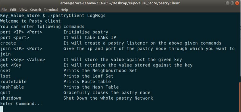
Figure 6 depicts the system screen after successful execution of all the above listed steps.
Initially, the port command is to be entered assigning an IP address and port to the node. Afterwards, enter the create command, which assigns a nodeId to the newly created node.
For example, the commands below will assign a port 9091 to the node with an IP 127.0.0.1.
port 127.0.0.1 9091
create
Similarly, you can run another node of the application on a different shell and assign a different port number. Join both the nodes using the join command as follows:
join 127.0.0.1 9091.
Multiple nodes can be added to the network. Put and get queries are done using the put and get commands.
Figure 7 demonstrates four running instances of the application with port number 9091, 9092, 9093 and 9094 all running on host 127.0.0.1. After creating and joining all nodes, demonstrate the put (key, value) operation, run put system1 Gaurav Arora on Node1 where system1 is the key and Gaurav Arora is the value associated with it. Then use the hashTable command to check which node this key-value pair gets stored in.
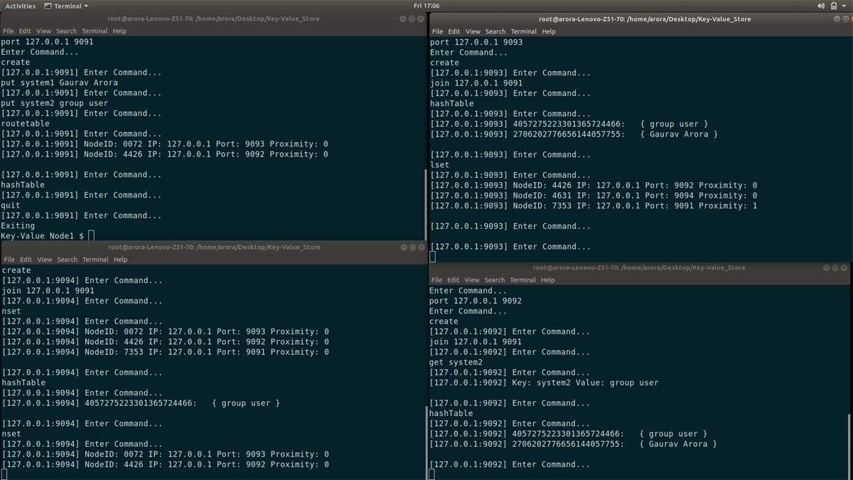
From Figure 7, it can be understood that the bottom-right and top-right terminal screens is where this value gets stored – i.e., Node3 and Node2, whereas the put operation is performed from Node1. This indicates that the messages get stored at the node with the nearest nodeId compared to the message’s key. Similarly, other operations like get have been demonstrated. Afterwards, quit one of the nodes, and see the modifications in the leaf set and neighbour set of the nodes.
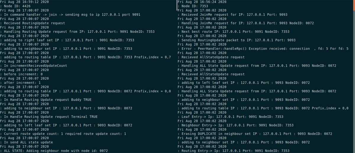
Figure 8 shows logs of two different nodes. Logs corresponding to the messages populated across nodes can be seen inside the figure.
Here, eventual consistency will be achieved and from Figure 7, it is evident that the key ‘system2’ is replicated across three nodes while the other key has been replicated only twice. This makes the application partition tolerant and fault-resilient.
This article elaborates the design for a decentralised, self-organising, scalable and fault-resilient distributed hash table, i.e., a key-value store with no single point of failure and equal responsibility distribution between all nodes, as in the case of a P2P system.
This implementation is based on C++. We used protocol buffers for communication and UNIX provided interfaces for accessing system resources. This design can be used as a basis for developing applications like messenger, publish-subscribe system where the publisher stores the list of subscribers and can efficiently route the message to subscribers, and global file sharing systems.


